Do you have a question about the Eurotherm Invensys 2408 and is the answer not in the manual?
Provides a general overview of the controller's features and availability.
Details the physical mounting and installation procedures for the controller.
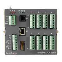
Covers the wiring and electrical connections for the controller and its modules.
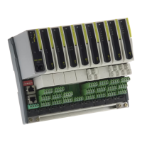
Explains the types and connections of various plug-in modules.
Describes the configuration and wiring for communication modules.
Details the wiring connections for DeviceNet communication.
Explains the wiring diagram and specifications for Profibus communication.
Presents a general wiring diagram illustrating typical controller connections.
Illustrates how to connect motorised valves to the controller.
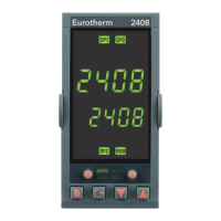
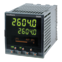
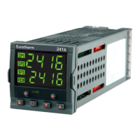
Describes the layout and function of buttons and indicators on the controller's front panel.
Explains the initial power-on sequence and the home display of the controller.
Details the different operating modes available for the controller.
Guides through operating the controller in automatic mode.
Guides through operating the controller in manual mode.
Explains how to navigate and access the controller's parameters.
Illustrates the parameter navigation structure for the controller.
Provides a comprehensive list of controller parameters and their meanings.
Outlines the four distinct access levels for controller parameters.
Explains the procedure for selecting and accessing different operational levels.
Details how to configure parameter visibility and alterability for operator access.
Explains the purpose and goals of controller tuning for optimal performance.
Describes the automatic tuning methods available for the controller.
Provides steps for manually adjusting tuning parameters using the Ziegler-Nichols method.
Details the configuration and commissioning of motorised valve control.
Explains how to implement gain scheduling for improved control performance.
Introduces setpoint programming and its application for time-varying setpoints.
Describes the different operational states of the programmer feature.
Details how to select and start programs using the run list.
Explains how to control program execution using the RUN/HOLD button.
Covers automatic features like Servo, Holdback, and Power Failure handling.
Guides through the initial configuration of the programmer settings.
Details the process of creating and editing setpoint programs.
Explains how to enter the controller's configuration mode.
Describes how to navigate and select configuration parameters.
Illustrates the parameter navigation structure for the controller.
Continues the illustration of the parameter navigation structure.
Shows the calibration-related parameter navigation structure.
Lists and explains various configuration parameters and their settings.
Explains the benefits and reasons for performing user calibration.
Details how to enable the user calibration feature in the controller.
Describes the process of applying a single fixed offset for calibration.
Explains how to perform a two-point calibration for accurate input measurement.
Covers general safety precautions and compliance with low voltage directives.
Addresses EMC requirements and compliance with relevant directives.
Provides guidance on servicing and repair procedures for the controller.
Details essential safety measures and requirements for controller installation.
Explains how to read load current and display modes.
Details how to configure alarm trip levels for load monitoring.
Guides on configuring PDS load current diagnostics for operational modes.
Explains how to set up low and high current trip alarms.
Describes how to adjust the scaling factor for current readings.
Provides an introduction to Profibus-DP communications for specific controller models.
Explains the Profibus-DP network standard and its applications.
Lists the technical specifications for Profibus-DP communication.
Offers solutions for common communication issues with Profibus networks.
| Display | Dual 4-digit LED |
|---|---|
| Mounting | Panel Mount |
| Input Type | Thermocouple, RTD |
| Output Type | Relay, SSR |
| Control Modes | On/Off, PID |
| Communication Protocols | DeviceNet, Profibus |
| Power Supply | 100-240V AC |
| Dimensions | 96 x 96 mm |
| Supply Voltage | 100-240V AC, 24V AC/DC |
| Control Algorithm | Adaptive tuning, Self-tuning |