Do you have a question about the Eurotherm 3508 and is the answer not in the manual?
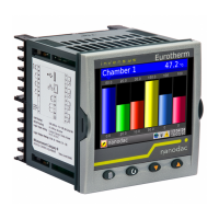
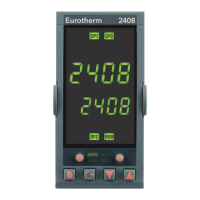
Identifies the controller model (3508/3504) and its intended use in industrial and laboratory processes.
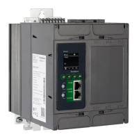
Details hardware coding and module options for ordering the controllers, crucial for configuration.
Explains the use of configuration codes for initial setup and instrument configuration.
Provides instructions for panel mounting, dimensions, and general safety information for installation.
Details rear terminal views for 3508/3504 models and specifies wire sizes for safe electrical connections.
Describes common connections for PV input types like Thermocouple, RTD, Linear V/mA.
Explains connections for various plug-in modules (relay, triac, logic, analogue) and their hardware codes.
Details connections for digital communication protocols like Modbus, DeviceNet, Profibus, and Ethernet.
Describes Level 3 access, making all operating parameters available and alterable for advanced adjustments.
Explains Configuration Level access for changing fundamental instrument characteristics and process matching.
Provides steps to navigate and select different security levels (1, 2, 3, Config) for accessing parameters.
Summarizes parameters available under the Access list header, including security codes and keylock functions.
Explains how to access function blocks and their associated parameters via the Page button.
Describes how lists are broken down into sub-headers for more comprehensive parameter views.
Guides on scrolling through parameters within a function block and selecting them for viewing or editing.
Illustrates the navigation diagram showing all function blocks available as list headings in configuration level.
Explains soft wiring, the software connections made between function blocks for custom strategies.
Demonstrates wiring a PID block output to a logic output, showing input and output parameter connections.
Provides step-by-step instructions for making wires between function blocks using the controller's interface.
Explains the procedure to remove existing wiring connections between parameters.
Outlines the capabilities of instrument configuration, including enabling function blocks, options, and display customization.
Provides steps to select configuration level and access instrument configuration options via the Access list.
Explains how to enable or disable function blocks, affecting parameter visibility based on application relevance.
Details parameters for setting up instrument options such as display units, programmer modes, and PV start.
Explains how to customize the display, including bar graph options.
Guides on selecting the Process Variable (PV) input and accessing related parameters in Level 3 or Configuration level.
Lists parameters for process input, including IO Type, Linearisation, Units, Resolution, and Fault Detection.
Details available input types like Thermocouple, RTD, Linear, and their corresponding ranges.
Explains Closed Junction Compensation (CJC) methods for thermocouple inputs.
Describes how sensor break is detected and indicated, including typical impedance values for trip detection.
Explains fallback strategies used for default PV values during error conditions like sensor break or out of range.
Details scaling of linear PV inputs to match displayed readings to electrical input levels from transducers.
Explains applying a single offset to the controller display range to compensate for process errors.
Describes enabling controller display offset at low and high ends of the scale for sensor or inter-connection error compensation.
Guides on selecting the Logic IO list and configuring channels as inputs or outputs.
Details parameters for logic IO configuration, including IO Type, Invert, Standby action, and output values.
Provides an example of configuring a logic output for time proportioning control.
Guides on calibrating a valve position output, including setting 'Cal State' for Raise and Lower points.
Guides on selecting the AA Relay list and configuring its function as On/Off or Time Prop.
Details parameters for AA Relay configuration, including Cycle Time, Min OnTime, and Standby action.
Demonstrates wiring the AA Relay output to an analogue alarm to operate when the alarm occurs.
Provides instructions on fitting I/O and communications modules into controller slots.
Explains how to identify the type of I/O module fitted in the controller slots via the 'ModIDs' page.
Lists parameters available for different modules (relay, logic, triac, DC control, analogue input).
Explains scaling analogue inputs and outputs, including applying offsets for calibration.
Guides on configuring the IO Expander, including selecting type and setting input/output parameters.
Details parameters for the IO Expander, covering status, input states, and output configurations.
Provides definitions for alarm terms like soft alarms, events, hysteresis, latching, blocking, and delay.
Explains analogue alarms, their types (Absolute High/Low, Deviation), and how they operate.
Details digital alarms that operate on Boolean variables and trigger messages on state changes.
Lists parameters for setting up analogue alarms, including type, input, reference, threshold, and output state.
Details parameters for setting up digital alarms, including type, input, output, inhibit, latch, and block.
Explains diagnostic alarms indicating possible faults within the controller or connected devices, with troubleshooting advice.
Guides on using iTools for configuring alarms and customizing alarm messages for the controller display.
Details parameters for the BCD input function block, including input/output values and data format.
Explains EIA232 and EIA485 serial communications protocols, including wiring connections and converters.
Details configuration ports like IR Clip, CFG Clip, and USB CPI Clip for instrument setup and communications.
Lists parameters for digital communications across various protocols (Modbus, Profibus, DeviceNet, Ethernet).
Explains Ethernet protocol parameters, including IP addressing, DHCP, network settings, and MAC address display.
Describes the Profibus DP protocol, its parameters, and wiring connections for high-speed digital communication.
Details the DeviceNet protocol, its parameters, and wiring connections for industrial I/O interconnection.
Explains the Comms Table for mapping parameters to SCADA addresses and configuring data formats.
Describes sending a single value from a master to multiple slave instruments using broadcast communications.
Explains the Modbus Master function block for generating communications from the instrument to slaves.
Describes counter function blocks, including up/down counting, cascading, and timing diagrams.
Explains timer function blocks and their modes: On Pulse, On Delay, One Shot, and Compressor/Minimum On Timer.
Details totaliser function blocks for recording numeric totals over time, including alarm attributes.
Describes the real-time clock for daily/weekly scheduling and alarm configuration.
Explains humidity control applications, including setpoint profiles and output configurations for refrigeration and heating.
Lists parameters for humidity control, covering psychrometric constant, pressure, wet/dry bulb temperatures, and relative humidity.
Describes Zirconia block functionality for carbon potential control, including temperature, mV input, and gas references.
Details Zirconia block parameters, including probe types, resolution, temperature limits, and fault indications.
Provides an example wiring diagram for carbon potential control, showing module usage.
Explains the function that continuously monitors input value and records the highest value.
Describes the function that continuously monitors input value and records the lowest value.
Details the function that increments a timer when input is above threshold, with alarm capabilities.
Lists parameters for input monitoring, including input source, limits, and status.
Explains logic operators for performing calculations on two input values (AND, OR, XOR, LATCH, etc.).
Describes eight input logic operators for performing calculations on up to eight inputs.
Details maths operators for performing mathematical operations on input values (add, subtract, multiply, divide, etc.).
Explains multiplexers used to switch one of eight inputs to an output, configurable via Inst Opt.
Describes the block performing analogue operations on up to eight inputs, outputting Sum, Average, Max, Min.
Explains how two Multiple Input Operator blocks can be cascaded to handle up to 16 inputs.
Details fallback strategies (Clip Good, Clip Bad, Fall Good, Fall Bad) for handling bad input status.
Explains the Lin16 function block for converting input signals to PV using up to 14 straight lines.
Details the polynomial function block for converting input signals using polynomial equations.
Lists parameters for load simulation blocks (Oven, Furnace), including type, resolution, gain, and time constants.
Provides a basic explanation of a control loop, including its components and operation.
Describes function blocks associated with control loops: Main, Setup, PID, SP, and Diagnostics.
Provides an overview of parameters for the overall control loop, allowing Auto/Manual operation and integral hold.
Explains configuration of control loop types (On/Off, PID, Valve Position) and direction (Reverse/Direct).
Details PID parameters like Proportional Band (PB), Integral Time (Ti), Derivative Time (Td), and Gain Scheduling.
Explains SyncStart, SyncAll, and Single Channel programmer modes for dual loop control.
Describes Time to Target and Ramp Rate programmer types for creating setpoint profiles.
Details segment types including Rate, Dwell, Step, Time, GoBack, Wait, and Call for program definition.
Explains PV Events and Time Events, used to trigger responses or digital outputs during program execution.
Describes holdback, freezing program execution if PV deviates from SP beyond a user-defined limit.
Explains how to set up and activate multiple PID sets for different segments within a program.
Details how sync points and GoBack segments coordinate execution between channels or instruments.
Explains setting the number of times a program repeats, from continuous to 9999 times.
Defines controller behavior after power restoration (Continue, Ramp back, Reset).
Guides on operating programs via front panel buttons, digital inputs, or digital communications.
Allows programs to automatically advance to the profile point corresponding to the current PV.
Covers parameters common to all programs for channels 1 and 2, configured in configuration level.
Explains how to set up or edit programs, including selecting segments, types, and target setpoints.
Provides an example of configuring a Rate segment followed by a Dwell segment for Single Channel/SyncStart programmers.
Demonstrates configuring a segment to wait for a digital input LA to become true before proceeding.
Shows how to repeat a section of a program using a GoBack segment with specified cycles.
Provides an example of running a dual programmer, including status indicators and parameter access.
Describes editing programs using iTools or SCADA communications.
Lists parameters available in earlier versions of the single programmer block for reference.
Provides steps to set switch over levels for temperature applications using different input devices.
Details parameters for switch over blocks, including input limits, switch boundaries, and fallback strategies.
Explains the auto-tare function for calibrating transducers, typically for weighing applications.
Describes the transducer summary page for viewing calibration status and accessing parameters.
Details strain gauge calibration procedures, including wiring and parameter configuration for accurate measurement.
Explains load cell calibration, including physical wiring and parameter configuration for weighing applications.
Describes calibration by comparison against a known reference instrument for accurate readings.
Lists parameters for configuring and calibrating transducer types, including Cal Type, Range, and Input/Output values.
Guides on checking input calibration for mV, thermocouple, and RTD inputs, including necessary precautions.
Provides steps for calibrating the mV range using a milli-volt source, including saving new calibration data.
Explains checking thermocouple input calibration using an mV source simulating thermocouple types.
Details checking RTD input calibration by connecting a decade box to simulate resistance values.
Outlines the inputs that can be calibrated (mV, thermocouple, RTD) and the general procedure.
Explains how to save new calibration data, making it permanent after a power down.
Describes how to load factory calibration values, reinstating the original settings.
Explains thermocouple calibration, including using external CJC reference sources or simulators.
Details RTD calibration at specific resistance points using a decade box.
Lists parameters available in the Calibration List, showing calibration states and their meanings.
Explains calibration of VP output associated with digital outputs driving valves.
Details calibration procedures for DC output and retransmission modules to ensure accurate monitoring.
Lists iTools features for instrument configuration, including parameter setup, device operation, and graphical wiring.
Explains changing parameters directly on the device or using simulations and saving to files.
Guides on connecting a PC to the controller using EIA232, EIA485, IR clip, or configuration clip.
Explains how to use iTools to scan for connected instruments and access their configuration.
Details configuring parameters using iTools, including changing values and accessing configuration mode.
Describes the Device Panel for remote viewing, diagnostics, and training, simulating the instrument display.
Explains creating and downloading custom display pages (up to 8 pages, 64 lines) to the controller.
Provides step-by-step instructions for creating user pages, selecting styles, parameters, and operator levels.
Shows controller display examples for different user page styles (Text, Value, Split Row, Bar Graph).
Describes the 'ImmPSP' parameter for promoting immediate setpoint changes to the controller display.
Explains the Recipe Editor for storing and loading operating values for different batches or processes.
Guides on setting up alarms, including customizing analogue and digital alarm messages.
Describes viewing alarm states, limits, comments, and adding custom alarm messages.
Explains using the editor to view, edit, and download instrument wiring, adding comments and monitors.
Details how to use function blocks by dragging them onto the diagram and wiring parameters.
Describes the process of downloading wiring, diagram layout, and settings to the instrument.
| Control Type | PID, On/Off |
|---|---|
| Input Types | Thermocouple, RTD |
| Output Types | Relay, DC Linear |
| Power Supply | 100-240V AC, 24V DC |
| Communications | Modbus |