Do you have a question about the Eurotherm Mini8 and is the answer not in the manual?
Specifies the hardware configuration and options for ordering the controller.
Provides instructions on physical mounting, dimensions, and environmental requirements.
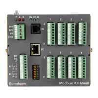
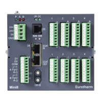
Details essential power and common connection points for all Mini8 instruments.
Covers wiring for Modbus communication protocol connections.
Covers wiring for DeviceNet and CANopen communication protocols.
Details connections for the enhanced DeviceNet interface.
Covers wiring for Profibus DP communication connections.
Details EtherNet connections for Modbus TCP communication.
Details EtherNet/IP connections for industrial automation.
Covers EtherCAT connections for industrial automation technology.
Details connections for TC4 and TC8 thermocouple input modules.
Details connections for RTD and Pt100 input modules.
Details connections for the DI8 8-channel digital input card.
Details connections for the DO8 8-channel digital output card.
Wiring considerations for switching inductive loads.
Details connections for the RL8 8-channel relay output card.
Details connections for AO4/AO8 4/8-channel analogue output cards.
Details connections for the CT3 3-channel current transformer input card.
Instructions for safely installing or removing input/output modules.
Explains the module and network status LEDs for the Enhanced DeviceNet interface.
Details the module and network status LEDs for EtherNet/IP communication.
Describes the status indication LEDs for EtherCAT modules.
Introduces iTools for configuration, commissioning, trend graphing, and logging.
Explains Modbus single register addressing for SCADA systems and PLCs.
Details how to navigate and interact with the iTools software for operation.
Describes OPCScope as an OPC client for real-time trend charts and data logging.
Explains the process of configuring the Mini8 controller for specific applications.
Covers the necessary cables and steps for connecting a PC for configuration.
Details saving and loading configuration files for instrument duplication.
Explains function blocks and soft wiring for building control strategies.
Demonstrates configuring the Mini8 controller with a PID loop and I/O.
Details the use of the graphical interface for wiring function blocks and parameters.
Explains the process of transferring the configured application to the instrument.
Lists all available function blocks and their corresponding chapters for detailed information.
Lists options that can be enabled within the instrument's configuration.
Provides information for fault finding and diagnostic checks on the instrument.
Lists and describes the identification values for installed I/O modules.
Covers the parameters and configuration for thermocouple and mV input modules.
Details the parameters and configuration for RTD and Pt100 input modules.
Explains the configuration of analogue output modules for mA signals.
Describes the capability for detecting heater load failures using current transformers.
Defines key alarm concepts like Hysteresis, Latch, Block, and Delay.
Explains the types of analogue alarms and their configuration.
Describes digital alarms based on Boolean variables and their types.
Details parameters for configuring analogue alarms, including type, threshold, and latching.
Details parameters for configuring digital alarms, including type, inhibit, and block.
Provides a summary of all alarms and their status indicators.
Explains how the alarm log maintains a history of recent alarms.
Describes the RJ11 configuration port for connecting to PCs and iTools.
Details the main communications port supporting various protocols like Modbus, DeviceNet, etc.
Covers Modbus RTU protocol, connections, address switches, baud rate, and parity.
Explains DeviceNet configuration parameters like baud rate and address.
Provides information on CANopen interface, instrument setup, and features.
Details EtherNet setup, IP addressing, DHCP, and preferred master configurations.
Covers EtherNet/IP communication system, feature switches, and iTools configuration.
Step-by-step guide for establishing communication between Mini8 and an Allen-Bradley PLC.
Explains EtherCAT technology, its parameters, and the EtherCAT-to-Modbus interface.
Provides a basic explanation of how a control loop functions in the controller.
Details parameters for selecting Auto/Manual operation, PV, and setpoint sources.
Covers configuration of control types, including On/Off and PID control.
Explains Proportional, Integral, Derivative terms, and cutback parameters.
Describes procedures for automatic and manual tuning of control loops.
Details how to configure setpoint sources, limits, rate limiting, and tracking.
Covers output limits, rate limiting, sensor break modes, and feedforward implementation.
Introduces the setpoint programmer for creating time-based profiles.
Explains the availability and association of programmer blocks with loops.
Details different segment types like Rate, Dwell, Step, Time, GoBack, and Wait.
Describes strategies for controller behavior upon restoration of power after an outage.
Explains general configuration settings for the Programmer Block.
Describes using the iTools Program Editor for creating and managing programs.
Explains the auto-tare function for calibrating inputs to remove container weight.
Details calibrating the controller against a second reference instrument.
Covers parameters for selecting calibration type, enabling calibration, and setting ranges.
Details how to enable, lock, and unlock the instrument using security features.
Describes the process of activating OEM security by entering a numerical code.
Lists operating temperature, humidity, storage conditions, and approvals.
Details supported network protocols and their baud rates.
Specifies electrical characteristics of fixed relay and logic input/output cards.
Provides electrical specifications for TC8 and TC4 thermocouple input cards.
Details electrical specifications for the 8-channel digital output card.
Provides electrical specifications for the 8-channel relay output card.
Details specifications for the 3-channel current transformer input card.
Explains the load failure detection capabilities using CT3 module.
| Type | Temperature Controller |
|---|---|
| Control Algorithm | PID |
| Analog Outputs | 1 |
| Mounting | Panel Mount |
| Input Types | Thermocouple, RTD |
| Output Types | Relay |
| Display | LCD |
| Control Modes | PID, On/Off |
| Communication Protocols | Ethernet |
| Power Supply | 24V DC |
| Dimensions | 96 x 96 x 80 mm (1/4 DIN) |
| Configuration | Front Panel |