Mini8™ CONTROLLER
INSTALLATION AND WIRING INSTRUCTIONS
HA028497/7 (CN27932)
Installation Category And Pollution Degree
This unit has been designed to conform to BS EN61010 installation category II
and pollution degree 2. These are defined as follows:
Installation category II. The rated impulse voltage for equipment on
nominal 230V ac mains is 2500V.
Pollution degree 2. Normally, only non-conductive pollution occurs.
However, occasionally a temporary conductivity caused by condensation
shall be expected.
Personnel
Installation MUST be carried out only by qualified personnel.
Enclosure Of Live Parts
To prevent hands or metal tools touching parts that may be electrically live,
the unit must be installed in an enclosure.
Wiring
It is important to connect the unit in accordance with the data on this
sheet, ensuring the protective Earth connection is ALWAYS fitted first and
disconnected last. Wiring MUST comply with local wiring regulations, e.g. in
the UK, the latest IEE wiring regulations (BS7671), or for the USA, NEC Class
1 wiring methods. Use only copper conductors for connections. Terminal
tightening torque 0.4Nm max.
Caution
Do not connect AC supply to low voltage sensor input or low level inputs and outputs.
Power Isolation
The installation must include a power isolating switch or circuit breaker.
This should be in close proximity to the unit (< 1 metre), in easy reach of the
operator and marked as the disconnecting device for the unit.
Overcurrent Protection
It is recommended that the power supply to the system be fused appropriately
to protect the cabling to the unit.
Conductive Pollution
Electrically conductive pollution, e.g. carbon dust, MUST be excluded from
the enclosure in which the unit is installed. To secure a suitable atmosphere in
conditions of conductive pollution, an air filter should be fitted to the air intake
of the enclosure. Where condensation is likely, a thermostatically controlled
heater should be included in the enclosure.
Over-temperature Protection
When designing a control system it is essential to consider the consequences
should any part of the system fail. In temperature control applications the
primary danger is the heating will remain constantly on. This could spoil the
product, but more seriously, it might damage the process machinery being
controlled, or even cause a fire.
Reasons for the heating remaining on continuously include:
1 The temperature sensor is detached from the process
2 The thermocouple wiring has short circuited
3 The unit has failed with the heating output constantly on
4 The external valve or contactor is sticking in the heating condition
5 Unit setpoint is set too high
Where damage or injury can occur, it is recommended that a separate
over-temperature protection unit, and an independent temperature sensor, to
isolate the heating circuit, be fitted.
Note Alarm relays within the unit do not indicate all failure conditions.
Installation Requirements For EMC
To comply with European EMC directive certain installation precautions are
necessary:
For general guidance, refer to EMC Installation Guide, part no. HA025464.
With relay outputs, it may be necessary to fit suitable filters to suppress
conducted emissions. Filter requirements depend on the type of load. Typical
applications may use Schaffner FN321 or FN612.
For table-top installation, if a standard power socket is to be used, compliance
with commercial and light industrial emissions standard is usually required.
To comply with conducted emissions standard, a suitable mains filter must be
installed, such as Schaffner FN321 or FN612.
INSTALLATION SAFETY REQUIREMENTS
Various symbols used on the instrument are described below:
Caution (refer to the
accompanying documents)
Protective
earth terminal
!
Functional
(ground) earth
MANUFACTURING ADDRESS
U.K. Worthing
Invensys Eurotherm Limited
Telephone: (+44 1903) 268500
Fax: (+44 1903) 265982
E-mail: info@eurotherm.co.uk
Web: www.eurotherm.co.uk
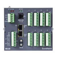
What is the Mini8 Controller?
The Mini8 Controller is a compact multi-loop PID controller
and data acquisition unit, offering a choice of I/O and field
communications and designed for mounting on a 35mm
‘Top Hat’ DIN Rail.
Pre-assembled in the factory, the controller is fitted with all
the I/O required for the application, as specified at time
of order. With standard applications the Mini8 Controller
can be supplied as a configured instrument or it can be
configured using iTools configuration software running on a
personal computer.
I/O Connection
Terminals
Power Supply
Communications
Connection Terminals
(version dependent)
Standard I/O
Connection
Terminals
Routing Of Wires
To minimise interference from electrical noise, low voltage DC connections and
sensor input wiring must be routed away from high-current power cables. If this is
not practical, use shielded cables, shield grounded at both ends, and keep cable
lengths to a minimum.
GENERAL
This unit is intended for Industrial Temperature and Process Control applications,
within the requirements of the European Directives on Safety and EMC.
Warning
The Safety and EMC protection provided can be seriously impaired, if the instru-
ment is not used in the manner specified. The installer MUST ensure the Safety and
EMC of all installations.
Unpacking And Storage
The packaging contains the unit, this sheet, and a CD. If on receipt, the packaging
or unit are damaged, do NOT install, but contact the supplier. If being stored
before use, protect from humidity and dust in an ambient temperature range of
-30ºC to +75ºC.
Caution: Electrostatic discharge
Always observe all electrostatic precautions, before handling the unit.
Service And Repair
The unit has no servicable parts. Contact the supplier for repair.
Cleaning
Isopropyl Alcohol may be used to clean the labels. (Labels will become illegible
if water or water based products are used.) A mild soap solution can be used to
clean other exterior surfaces.
RoHS statement
© Copyright Eurotherm Limited™ 2010
All rights are strictly reserved. No part of this document may be reproduced, modified, or
transmitted in any form by any means, nor may it be stored in a retrieval system other than for
the purpose to act as an aid in operating the equipment to which the document relates, without
the prior written permission of Eurotherm Limited.
Eurotherm Limited pursues a policy of continuous development and product improvement.
The specification in this document may therefore change without notice. The information in
this document is given in good faith, but is intended for guidance only. Eurotherm Limited will
accept no responsibility for any loses arising from errors in this document.
COMMUNICATIONS
Communications connection
terminals are version dependent;
see overleaf for details.
RT4 - 2, 3, 4 Wire RTD Input
ISOLATION
Channel to Channel: 42V pk.
Channel to system: 42V pk.
Legend Function
A ..... CH1 I+
B ..... CH1 S+
C ..... CH1 S-
D ..... CH1 I-
E ..... CH2 I+
F . . . . . CH2 S+
G ..... CH2 S-
H ..... CH2 I-
I . . . . . CH3 I+
J . . . . . CH3 S+
K ..... CH3 S-
L . . . . . CH3 I-
M ..... CH4 I+
N ..... CH4 S+
O ..... CH4 S-
P . . . . . CH4 I-
Wire
Connections
2 3 4
Legend Function
A ..... TC1+
B ..... TC1-
C ..... TC2+
D ..... TC2-
E ..... TC3+
F . . . . . TC3-
G ..... TC4+
H ..... TC4-
I . . . . . TC5+
J . . . . . TC5-
K ..... TC6+
L . . . . . TC6-
M ..... TC7+
N ..... TC7-
O ..... TC8+
P . . . . . TC8-
TC8/TC4
-Thermocouple Input
Note.
TC4 supports Channels 1
to 4 only.
ISOLATION
Channel to Channel: 42V
pk.
Channel to system: 42V pk.
Legend Function
A ..... N/A
B ..... N/A
C ..... N/A
D ..... N/A
E ..... N/A
F . . . . . N/A
G ..... N/A
H ..... N/A
I . . . . . In1 A
J . . . . . In1 B
K ..... No connection
L . . . . . In2 A
M ..... In2 B
N ..... No connection
O ..... In3 A
P . . . . . In3 B
CT3 - Current
Transformer Input
ISOLATION
Channel to Channel - N/A
Channel to system - N/A
Note. Isolation provided by
current transformers.
DO8 - Logic Output
Note. Requires 24Vdc supply.
ISOLATION
Channel to Channel - N/A
Channel to system: 42V peak
with independant supply
Note. * - Linked internally.
Legend Function
A ..... Supply In +
B ..... Supply In +
C ..... OP1 +
D ..... OP2 +
E ..... OP3 +
F . . . . . OP4 +
G ..... Supply & OP-
H ..... Supply & OP-
I . . . . . Supply In +
J . . . . . Supply In +
K ..... OP5 +
L . . . . . OP6 +
M ..... OP7 +
N ..... OP8 +
O ..... Supply & OP-
P . . . . . Supply & OP-
RL8 - Relay Output
(slots 2 and/or 3 only)
Contact voltage/current - 264Vac/2A
RMS max.
ISOLATION (264VAC BASIC)
Channel to Channel - 264Vac basic
Channel to system - Reinforced
Note. Protective earth conductor MUST
be used if RL8 module is fitted.
Legend Function
A ..... RLY1 A
B ..... RLY1 B
C ..... RLY2 A
D ..... RLY2 B
E ..... RLY3 A
F . . . . . RLY3 B
G ..... RLY4 A
H ..... RLY4 B
I . . . . . RLY5 A
J . . . . . RLY5 B
K ..... RLY6 A
L . . . . . RLY6 B
M ..... RLY7 A
N ..... RLY7 B
O ..... RLY8 A
P . . . . . RLY8 B
DI8 - Logic Input
Note. Input specification
as for ‘Standard I/O’
above.
ISOLATION
Channel to channel: 42V pk.
Channel to system: 42V pk.
Legend Function
A ..... D1+
B ..... D1-
C ..... D2+
D ..... D2-
E ..... D3+
F . . . . . D3-
G ..... D4+
H ..... D4-
I . . . . . D5+
J . . . . . D5-
K ..... D6+
L . . . . . D6-
M ..... D7+
N ..... D7-
O ..... D8+
P . . . . . D8-
*
*
Legend Function
A ..... OP1+
B ..... OP1-
C ..... OP2+
D ..... OP2-
E ..... OP3+
F . . . . . OP3-
G ..... OP4+
H ..... OP4-
I . . . . . OP5+
J . . . . . OP5-
K ..... OP6+
L . . . . . OP6-
M ..... OP7+
N ..... OP7-
O ..... OP8+
P . . . . . OP8-
AO8/AO4 - Analog
Output (slot 4 only)
Output current - 0 to 20mA,
360 ohm max load.
Note. AO4 supports Channels 1
to 4 only
ISOLATION
Channel to Channel: 42V pk.
Channel to system: 42V pk.
Caution
The Mini8 Controller is intended for operation at safe low voltage levels, except the Relay
Module. Voltages in excess of 42V dc must NOT be applied to any terminals other than the
Relay Module, RL8.
A protective Earth connection is required. ALWAYS ensure that the protective Earth is fit-
ted first and disconnected last.
Do NOT replace the battery. Return the unit to the factory if replacement is required.
Legend Function
D1 . . . . . . . . . . Digital Input 1
D2 . . . . . . . . . . Digital Input 2
C ...........Digital Input Common
A1 . . . . . . . . . . Relay A n/open
A2 . . . . . . . . . . Relay A n/closed
A3 . . . . . . . . . . Relay A Common
B1 . . . . . . . . . . Relay B n/open
B2 . . . . . . . . . . Relay B n/closed
B3 . . . . . . . . . . Relay B Common
Note: Digital Inputs:
-28.8V to +5V = Off
+5V to +10.8V = undefined
+10.8V to +28.8V = On
Typ. drive current: 2.5mA
@10.8V
Relay Contacts:
1 Amp max, 42V dc max.
Power Supply
This terminal can accept wire sizes 0.2 - 2.5mm (24 - 12 awg).
Legend Supply
24V 24V dc
24V 24V dc
0V 0V
GND Ground
Linked
POWER SUPPLY SPECIFICATION
Power supply voltage: 17.8Vdc min to 28.8Vdc max
Power comsumption: 15W max
Standard I/O Connections
Communications Interface Leds
!
LEDs
Legend Colour Function Action
P Green Indicates Power status On - Power On
Off - Power Off
A Red Indicates Relay A state On - Energised
Off - De-Energised
B Red Indicates Relay B state On - Energised
Off - De-Energised
Leg. Col. Function Action
RN Green Run mode On - Running
Blinking - Standby/Config
Off - Not Running
CC Green Configuration activity On - N/A
Blinking - Config Traffic
Off - N/A
FC Green Field Comms activity On - Connected
Blinking - Ready
Off - Offline
Off - No traffic or offline
Blinking - Comms Traffic
NET Bi-Col Network Status Off - Offline
(Enhanced DeviceNet Only) Blinking Green - Online but no connections
On Green - Online with connections
Blinking Red - Connection timed out
On Red - Total connection failure
Blinking Red/Green - Comms fault
MOD Bi-Col Module Status Off - Power not supplied to network
(Enhanced DeviceNet Only) On Green - DeviceNet interface operational
On Red - Power not supplied to controller
or Checksum failure
Blinking Red/Off - Recoverable fault. Comms.
error between network and DeviceNet interface.
Blinking Red/Green - Power-up tests, failure
to enter cyclic states or invalid Baud rate
Non-enhanced
DeviceNet® and CANopen
Modbus, Profibus,
and Ethernet