Do you have a question about the Eurotherm 2604 and is the answer not in the manual?
Defines the 2604 controller as a modular, configurable, high accuracy, high stability temperature and process controller.
Provides essential preliminary steps and checks before installing and operating the controller, including unpacking and verifying contents.
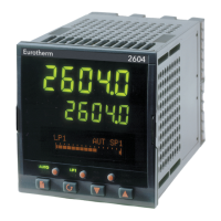
Describes the front panel layout, including displays, indicators, and operator buttons for interacting with the controller.
Outlines the general process and considerations for mounting and wiring the controller.
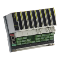
Details the facility to fit optional plug-in modules for expanding the controller's input/output capabilities.
Covers physical aspects of installing the controller, including positioning, dimensions, and mounting requirements.
Explains electrical connections, rear terminal layout, and wiring procedures for various inputs and outputs.
Details wiring for standard features like power supply, relay output, sensor inputs, and digital I/O.
Describes connections for optional communication and I/O modules, expanding controller functionality.
Provides specific instructions for connecting a Zirconia dual signal probe, including screening.
Explains the initial startup sequence, self-test, and the default HOME page display of the controller.
Details the function and operation of each button on the controller's front panel for user interaction.
Explains the Auto and Manual modes of operation and how to switch between them using the dedicated button.
Describes the functions of the RUN/HOLD button for controlling programmer operation, including starting, holding, and resetting.
Explains how to navigate and select different control loops (LP1, LP2, LP3, AUX) for viewing and operation.
Guides users on navigating through pages, sub-headers, and parameters to view and change settings.
Details how displays change for specific loop configurations like Cascade, Ratio, Override, and Valve Position.
Describes the shortcut for stepping back through list headers in navigation.
Describes the shortcut for stepping back through parameters in a list.
Explains how to quickly return to the default HOME screen display.
Discusses scenarios where key presses are invalid and what happens in those cases.
Explains factors affecting parameter visibility and whether they can be changed by the user.
Explains that parameter names can be customized by the user in configuration access level.
Introduces setpoint programming, defining profiles, segments, and their application in varying setpoints over time.
Defines key terms and parameters related to setpoint programmer operation, such as Run, Hold, Reset, Servo, etc.
Describes the two main programmer configurations: Time to Target and Ramp Rate.
Explains different segment types used in programs: Profile, Go Back, and End segments.
Lists programmer features that are detailed in a separate Engineering Handbook.
Covers the basic operation of running, holding, or resetting a program using the controller.
Guides users on the process of creating new programs or modifying existing ones.
Provides practical examples of data entry for different programmer types and features.
Defines what alarms and events are, differentiating between hard alarms and soft alarms.
Graphically illustrates different alarm types like Full Scale, Deviation, and Rate of Change.
Explains how alarms are visually indicated on the controller, including beacons and messages.
Describes how to access and view the Alarm Summary page for an overview of alarm statuses.
Details the methods for acknowledging alarms, including Auto and Manual reset procedures.
Guides users on configuring alarm setpoints and other related parameters.
Lists and describes specific alarm parameters available for loops, inputs, and modules.
Explains the modular hardware construction and how to interpret the hardware code.
Describes how controllers may be pre-configured using a specific coding system.
Provides an example of a quick start code to illustrate hardware specification.
Details safety compliance, including electromagnetic compatibility and relevant directives.
Provides information on servicing, repair, and precautions like charged capacitors and ESD.
Outlines essential safety requirements for controller installation, including symbols, personnel, and isolation.
Specifies precautions for installation to ensure compliance with EMC directives, including wiring practices.
Lists specifications for various input types, including sample rate, filtering, and calibration.
Provides detailed specifications for precision PV inputs and modules, including ranges, calibration, and drift.
Details specifications for the dual (probe) input module, including its general behavior and isolation.
Specifies the analogue input characteristics, including number of inputs, range, isolation, and functions.
Lists specifications for analogue input modules, covering allocation, ranges, calibration, and impedance.
Describes the specifications for standard digital inputs and outputs, including voltage levels and contact ratings.
Details specifications for digital input modules, including contact closure and logic input characteristics.
Lists specifications for digital output modules, including relay, triac, and logic outputs.
Provides specifications for analogue output modules, including range, resolution, and accuracy.
Details the specifications for the transmitter power supply module.
Lists specifications for the transducer power supply module, including bridge voltage and resistance.
Provides specifications for the dual DC output module, including current output, accuracy, and speed.
Details specifications for the high-resolution DC output module, including accuracy and speed.
Lists specifications for the potentiometer input, including resistance and excitation voltage.
Provides specifications for digital communication modules, including Modbus and Profibus-DP.
Lists the number and types of alarms supported by the controller, and parameters related to alarms.
Specifies the number and format for user-defined messages on the controller.
Outlines the available control modes, options, and algorithms for the controller.
Details the capabilities of the setpoint programmer, including program count, segment limits, and naming.
Lists advanced functions like application blocks, calculations, timers, and pattern generators.
Provides overall technical specifications for the controller, including display, environment, and dimensions.
Shows graphical representations of input errors, combining calibration, drift, linearity, and leakage.
| Display | 5-digit, 7-segment LED |
|---|---|
| Dimensions | 96 x 96 mm |
| Mounting | Panel mount |
| Control Type | PID |
| Input Types | Thermocouple, RTD |
| Output Types | Relay, DC Linear |
| Controller Type | Single loop |
| Communication | DeviceNet, Profibus |
| Supply Voltage | 100-240V AC, 24V AC/DC |