Do you have a question about the Eurotherm Nanodac and is the answer not in the manual?
Details requirements for permanently connected equipment and fuse ratings.
Covers enclosure, conductive pollution, mains supply fuses, and protective earth connections.
Discusses network design principles and DMZ for controller placement.
Highlights features like HMI access levels, passwords, Ethernet security, and backup.
Details security measures for FTP, ICMP, DHCP, SNTP, Modbus, HTTP, and BACnet.
Details the procedure for mounting the instrument through a panel cutout and securing it.
Covers termination details, low voltage options, dual input options, and communication wiring.
Describes how to review recorded data, including navigation and history options.
Configures network settings including Interface, Archiving, FTP, Modbus, and BACnet.
Configures parameters for analogue and digital inputs, including type, range, and alarms.
Sets up two control loops, covering PID, tuning, setpoint, and output parameters.
Enables advanced control options like cascade loops, PID tuning, and feedforward.
Configures setpoint programs with one or two channels, including segment editing and execution.
Configures the instrument to act as a Modbus master for communication with slaves.
Sets up an EtherNet/IP communications link with server units.
Steps to connect iTools to the PC and instrument.
Software tool for creating wiring diagrams.
Software tool for viewing and editing parameters.
Software tool for configuring setpoint programs.
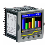
Detailed electrical and physical specifications of the recorder.
Explains Auto/Manual, PID, On/Off, and Valve Position control types.
Covers auto-tuning and manual tuning procedures for PID controllers.
| Operating Temperature | 0 to 50°C |
|---|---|
| Input Types | Thermocouple, RTD, mA, V, mV |
| Number of Universal Inputs | 4 |
| Control Loops | Up to 4 |
| Data Logging | Internal Flash, USB |
| Communication | Ethernet, USB, RS-485 |
| Power Supply | 24 V DC or 100-240 V AC |
| Dimensions | 96 x 96 x 90mm |
| Number of Outputs | Up to 4 |
| Output Channels | Relay, SSR |
| IP Rating | IP65 (front panel) |
| Accuracy | ±0.1% of reading |