Do you have a question about the Eurotherm 2416 and is the answer not in the manual?
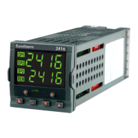
Covers terminal layouts, fixed connections, plug-in modules, and communications wiring.
Explains automatic, manual, and other modes, plus how to access and change parameters.
Comprehensive tables detailing controller parameters, their meanings, and values.
Explains alarm types, modes, annunciation, and diagnostic fault messages.
Details the procedure for accessing different security levels using passwords.
Explains how to configure parameter visibility and alterability for Operator level.
Covers one-shot and adaptive tuning, including typical cycles and error handling.
Details manual tuning (Ziegler-Nichols) and setting cutback values for overshoot control.
Commissioning and tuning procedures for motorised valve controllers, including inertia and backlash settings.
Explains how to enable and configure gain scheduling for PID parameter switching.
Guides on running programs from the run list and using the RUN/HOLD button for control.
Step-by-step guide for creating new programs or modifying existing ones, including segment types and parameters.
Covers displaying heater alarms, setting trip levels, activating diagnostic alarms, and configuring PDS/current trip alarms.
Details safety symbols, personnel requirements, enclosure of live parts, and wiring precautions.
| Control Type | PID |
|---|---|
| Input Types | Thermocouple, RTD |
| Output Types | Relay, SSR |
| Display | LED |
| Communication | Modbus |
| Supply Voltage | 100-240V AC, 24V DC |