Do you have a question about the Eurotherm 2500 and is the answer not in the manual?
Outlines safety symbols, personnel, enclosure of live parts, wiring, power isolation, earth leakage, and overcurrent protection.
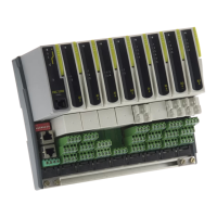
Details the mounting options for the 2500 base unit, including DIN rail and panel mounting.
Describes the different operating modes of the IOC: Run, Config, Standby, and Fail.
Details the RJ11 configuration port for connecting to a PC for setup and communication.
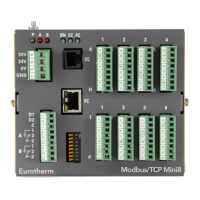
Describes the Modbus IOC module, its terminal unit, and network connections.
Details the Profibus IOC module, its terminal unit, and network connection options.
Covers the DeviceNet IOC module, its terminal unit, and connectivity.
Explains the Ethernet IOC module, its terminal unit, and network communication setup.
Describes three methods for connecting the 2500 system to a PC for configuration.
Details how to set the IOC access level to Operating, Configuration, or Standby modes.
Describes how to configure application solutions using function blocks and software wiring.
Details how to set up and configure loop operating parameters in Configuration Mode.
Explains the Proportional, Integral, and Derivative (PID) control terms and their functions.
Explains how to match controller characteristics to the process for optimal control.
Describes the automatic tuning process that induces oscillations to calculate parameters.
Details parameters for setting up digital communication interfaces.
Outlines the process of configuring the IOC to recognize modules and set up I/O channels using iTools.
Explains Modbus parameter addresses, including offsets and the need for incrementing for Modbus masters.
Details Profibus DP and DPv1 options, terminal unit styles, and network cabling requirements.
Describes a two-point gain and offset correction using PV offsets ('OfsetL', 'OfsetH') at two PV points ('PointL', 'PointH').
Explains reference calibration for eliminating residual system errors by changing electrical signal conversion at terminals.
| Brand | Eurotherm |
|---|---|
| Model | 2500 |
| Category | Controller |
| Language | English |