Do you have a question about the Eurotherm 2704 and is the answer not in the manual?
| Control Type | PID, On/Off |
|---|---|
| Input Types | Thermocouple, RTD, mA, V |
| Output Types | Relay |
| Communication | Modbus |
| Dimensions | 96 x 96 mm |
| Alarms | 2 programmable alarms |
| Display | LED Display |
| Supply Voltage | 100-240V AC, 24V AC/DC |
Defines the purpose and scope of instrument configuration.
Guides on enabling and configuring controller options.
Parameters to enable or disable instrument options like loops, programmer, etc.
Provides examples of renaming loops, alarms, and modules.
Explains the concept of setpoint programming and profiles.
Defines key parameters like Run, Hold, Reset, Servo, Hot Start.
Discusses Time to Target and Ramp Rate programmer types.
Details the Profile, Go Back To, and End segment types.
Outlines strategies for controller behavior after power restoration.
Explains how holdback freezes programs to ensure correct soak periods.
Describes how user values provide multiplexor facilities for event values.
Explains how digital inputs can control program operation.
Describes how to lock programs to prevent changes in operation levels.
Step-by-step guide to configure a synchronous programmer.
Describes how to configure a Ramp Rate type programmer.
Explains how to soft wire programmer function blocks to other functions.
Details the process of defining parameters for the overall program.
Guides on accessing the PROGRAM EDIT pages.
Explains how to set up each segment within a program.
Procedure for running a synchronous program.
Procedure for holding a program.
Procedure for resetting a program.
How to view the state of digital outputs or times remaining.
Examples of programmer wiring configurations.
Summary of functions available in the asynchronous programmer.
Explains how to set up and configure Program Groups.
Step-by-step guide to configure an asynchronous programmer.
How to configure a Ramp Rate type programmer.
Pages for configuring and setting up each PSP.
Steps to set up and run program groups.
Procedure for copying a program.
How to insert a segment into a program.
Displays error messages for invalid entries during program setup.
How to run asynchronous programs using PROG button or digital inputs.
Step-by-step guide to run a program using the PROG button.
Covers positioning and outline dimensions for mounting the controller.
Details the optional plug-in modules for communications and I/O.
Crucial section on electrical connections and rear terminal layout.
Wiring for analogue inputs accepting 0-10Vdc or mA signals.
Details on using an I/O expander for additional digital I/O points.
Configuration options for standard digital I/O connections.
Covers connections for digital communication modules.
Connects a Zirconia probe to a Dual PV Input module.
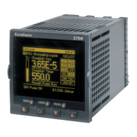
Describes the front panel display and seven operator push buttons.
How parameters are organized into pages and accessed.
Provides an overview of how to navigate through the controller's menus.
How parameter values are displayed and changed based on type.
Explains the structure and content of parameter tables.
Discusses parameter availability and conditions for alteration.
Visual representation of available pages and navigation paths.
Explains configuring control loops for various strategies.
Configuring a simple single loop, single output controller.
Defines the controller setpoint and its sourcing alternatives.
Technique for stable control using Proportional, Integral, Derivative terms.
Automatic transfer of control between PID values in non-linear systems.
Parameters that control the output to the plant.
Algorithm for positioning motorised valves.
Provides information on current operating conditions.
Configures the Loop Summary display.
Advanced control technique for fast response to disturbances.
Controls process variable at a setpoint calculated as a proportion of a lead input.
Secondary loop overrides main output to prevent undesirable conditions.
How to tune the controller for optimal process control.
Tuning cascade loops using master and slave controllers.
Controls temperature and carbon potential using zirconia probes.
How to view and adjust zirconia probe parameters.
Example wiring for zirconia probe connection.
Standard feature for humidity and altitude control applications.
How to view and adjust humidity control parameters.
Example wiring for humidity control loop.
Controls vacuum levels for various applications.
Features of the vacuum controller.
Wiring depends on modules fitted.
Install, wire, and configure controller, then switch on.
How to access vacuum controller parameters in access level 3.
Lists parameters available in all levels.
How to choose controller operation, display format, and names.
Examples of vacuum controller wiring.
Explains how input operators are used for process control.
Applies custom linearisation to inputs for accuracy.
How to view and adjust input operator parameters.
Switches inputs between thermocouple types or pyrometer.
Sets up monitor parameters for logging excursions and time.
Binary Coded Decimal function block for selecting program numbers.
Examples of wiring input operators.
Explains how timer blocks use time/date information for control.
Details the four operating modes for timer blocks.
How to configure timer type and set parameters.
Real-time clock for use with timer functions.
Alarms that allow output on/off at a set time and day.
Used to measure total quantity of a measurement integrated over time.
Selects groups of digital values from a single input number.
Allows selection of analogue values from an input number.
Constants used in analogue or digital operations.
Pop-up windows displayed as a result of a particular action.
Similar to User Values but for digital operations.
Allows parameter values to be enumerated with custom text.
Allows placing pre-determined parameters onto semi-custom screens.
Describes eight available screen styles for user pages.
Guides on configuring User Pages, including page location and style.
Associates auto/manual operation with the displayed user page.
Parameter tables for different user page types.
Allows mathematical operations on two input values.
Guides on configuring analogue operators and their parameters.
Performs analogue operations on up to six inputs.
Enables Analogue and Logic Operators in configuration level.
Locates parameters for multi-operators.
Lists the logical calculations that can be performed.
Guides on configuring logic operators and their parameters.
Allows wiring from any parameter to another.
Explains controller communication with PCs or networked systems.
Guides on configuring parameters for H and J Modules.
Monitors message increments and timeouts for comms modules.
Notes on MAC address, DHCP, instrument setup, and network connection.
Information specific to controllers with Ethernet communications.
Objective of master communications for 2704 controller.
Wiring for digital communication modules.
Checking cross-board version before configuring master comms.
Summary of how to navigate through master communications pages.
Steps to configure a transaction between master and slave parameters.
Steps to configure slave parameters.
Refers to fixed I/O connections and adjustment of limits, filter times, and scaling.
Accesses parameters for the fixed Process Variable Input.
Accesses parameters for the fixed Analogue Input.
Accesses parameters for the fixed Relay output.
Parameters to configure the fixed relay output.
Parameters to set up the fixed digital IO.
Inspects status or diagnostics of digital input/IO Expander.
Explains additional analogue and digital IO provided by plug-in modules.
Shows how to identify fitted modules by their type and slot.
Accesses parameters specific to each fitted module.
Specific module for TDS measurement.
How to scale IO modules.
Examples of wiring different IO modules.
Software function to offset controller input calibration.
Switching a calibration resistor across a measurement bridge.
Calibrating load cells connected to PV, Analogue, or Module inputs.
Calibrating controller against a second reference instrument.
Used for weighing container contents without the container.
Parameters for soft wiring sources for calibration.
External unit to increase digital IO points.
Setting up parameters to determine IO Expander operation.
Provides information on the internal state of the controller.
Allows instrument calibration against a certified field source.
Safety precautions before starting calibration procedures.
Calibrating the fixed PV input.
Calibrates the fixed Analogue Input.
Calibrates DC Output, Relay Output, Triac Output, and Logic Output modules.
Restores controller calibration to factory default values.
Controls water impurities in industrial boilers.
Defines TDS and its measurement in parts per million (PPM).
Factors influencing electronic TDS measurement.
Incorporates factors influencing TDS PV derivation.
Removes sludge and precipitated solids from boiler bottom.
Specific module for TDS measurement.
Controller complies with European Low Voltage Directive and safety standards.
Conforms to EMC Directive requirements.
Manual information subject to change; unpacking and storage.
Controller has no user serviceable parts; contact supplier for repair.
Safety requirements for installation.
Specifications for analogue, dual, and PV inputs.
Details for precision PV input modules.
Specification for dual input modules.
Specifications for analogue inputs.
Specifications for analogue input modules.
Allocation and types of standard digital I/O.
Types and allocation of digital input modules.
Types and allocation of digital output modules.
Types and allocation of analogue output modules.
Specification for transmitter power supply modules.
Specification for transducer power supply modules.
Specifications for dual DC output modules.
Specifications for high resolution DC output modules.
Specifications for potentiometer input modules.
Specifications for TDS modules.
Specifications for 4-Wire RTD input modules.
Allocation and types of digital communication modules.
Lists commonly used parameters with their Modbus addresses.
Lists available parameter units.
Displays status messages for modules.