Home
Eurotherm
Controller
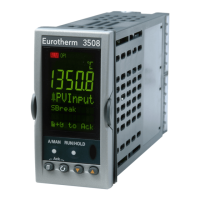
3508
Eurotherm 3508 Engineering Handbook
262 pages
Manual
Specs
Ask a question
To Next Page
To Next Page
Loading...
Engineering
handbook
ENG
3508
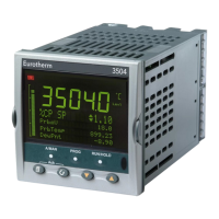
3504
PROCESS
CONTROLLERS
2 rue René Laennec 51500 Taissy France
Fax: 03 26 85 19 08, Tel : 03 26 82 49 29
E-mail:hvssystem@hvssystem.com
Site web : www.hvssystem.com
2
Table of Contents
Default Chapter
2
Table of Contents
2
Chapter 1 Installation and Operation
11
And 3508 Ordering Code
12
How to Install the Controller
13
To Install the Controller
14
Electrical Connections
15
Standard Connections
16
Digital I/O
17
Power Supply Connections
18
Plug in I/O Module Connections
19
Zirconia Probe Construction
23
Digital Communications Connections
24
Devicenet Wiring
25
Profibus
26
I/O Expander (or Additional Digital Input)
27
Example Wiring Diagram
28
Getting Started
29
Quick Start Parameters
31
To Re-Enter Quick Start Mode
34
Normal Operation
35
The Operator Buttons
36
To Set the Required Temperature (Setpoint)
37
Alarm Indication
38
Message Centre
39
How to Edit Parameters
40
Programmer Summary
41
Alarm Summary
43
Control Summary
44
Chapter 2 Access to Further Parameters
45
To Select Different Levels of Access
46
Access Parameter List
47
Chapter 3 Function Blocks
49
To Access a Function Block
50
To Change the Value of a Parameter
51
Navigation Diagram
52
Chapter 4 Function Block Wiring
53
Soft Wiring
54
Wiring through the Operator Interface
55
To Remove a Wire
56
Wiring a Parameter to Multiple Inputs
57
Wiring Floats with Status Information
58
Edge Wires
60
Operation of Booleans and Rounding
61
Chapter 5 Instrument Configuration
62
Options Available in the Instrument Configuration List
63
Display Formatting
64
Bar Graph (3504 0Nly)
66
Instrument Diagnostics
67
Chapter 6 Process Input
69
Input Types and Ranges
71
CJC Type
72
Display Units
73
PV Offset
74
PV Input Scaling
75
Chapter 7 Logic Input/Output
77
Example: to Configure a Time Proportioning Logic Output
78
Logic Output Scaling
79
Part no HA027988 Issue 3.0 Aug
80
Chapter 8 Aa Relay Output
81
Example: to Wire the AA Relay to an Alarm
82
Chapter 9 Module Configuration
83
Module Identification
85
Single Isolated Logic Output
87
DC Control Output or DC Retransmission
88
Analogue Input
89
Input Types and Ranges
91
Triple Logic Input and Triple Contact Input
92
Transmitter Power Supply
93
Transducer Power Supply
94
Module Scaling
95
Relay, Logic or Triac Output Scaling
96
Potentiometer Input Scaling
97
Chapter 10 Io Expander
99
To Configure the Io Expander
100
Chapter 11 Alarms
101
Analogue Alarms
102
Digital Alarms
103
How Alarms Are Indicated
104
Alarm Parameters
105
Example: to Configure Alarm 1
106
Diagnostic Alarms
107
Bcd Input
109
Example: to Wire a BCD Input
110
Digital Communications
111
Rs485
112
Configuration Ports
113
Broadcast Master Communications
114
Wiring Connections - Broadcast Communications
115
Digital Communications Parameters
116
Communications Identity
117
Example 2: to Send Sp from the Master to Pv in a Slave
118
Ethernet
119
Itools Setup
120
Counters, Timers, Totalisers, Real Time Clock
121
Counter Parameters
122
Timers
123
Off Delay Timer Mode
124
One Shot Timer Mode
125
Compressor or Minimum on Timer Mode
126
Timer Parameters
127
Totalisers
128
Real Time Clock
130
Application Specific
131
Temperature Control of an Environmental Chamber
132
Humidity Parameters
133
Zirconia (Carbon Potential) Control
134
Zirconia Parameters
135
Example of Carbon Potential Control Connections
136
Input Monitor
137
Input Monitor Parameters
138
Chapter 17 Logic and Maths Operators
139
Logic Operations
140
Logic Operator Parameters
141
Eight Input Logic Operators
142
Maths Operators
143
Math Operations
144
Math Operator Parameters
145
Sample and Hold Operation
146
Eight Input Analog Multiplexers
147
Chapter 18 Input Characterisation
149
Compensation for Sensor Non-Linearities
150
Input Linearisation Parameters
151
Polynomial
152
Chapter 19 Load
155
Chapter 20 Control Loop Set up
157
Loop Parameters - Main
158
Types of Control Loop
159
Pid Control
160
Integral Term
161
Loop Break Time
162
PID Parameters
163
Tuning
164
Manual Tuning
165
Tune Parameters
166
Setpoint Function Block
167
SP Tracking
168
Output Function Block
170
Power Feed Forward Enable
173
Output Limits
174
Effect of Control Action, Hysteresis and Deadband
175
Chapter 21 Setpoint Programmer
177
Programmer Operating States
178
Holdback (Guaranteed Soak)
179
Segment Types
180
Power Fail Recovery
181
Sync Mode
182
Creating or Editing a Program
183
To Select, Run, Hold or Reset a Program
186
Chapter 22 Switch over
187
Switch over Parameters
188
Chapter 23 Transducer Scaling
189
Strain Gauge
190
Comparison Calibration
191
Transducer Scaling Parameters
192
Parameter Notes
193
Transducer Summary
194
Strain Gauge
195
Load Cell
196
Comparison Calibration
197
Chapter 24 User Values
199
Chapter 25 Calibration
201
To Calibrate MV Range
202
To Save the New Calibration Data
203
Thermocouple Calibration
204
RTD Calibration
205
Calibration Parameters
206
Part no HA027988 Issue 3.0 Aug
208
Chapter 26 Configuration Using Itools
209
Connecting a Pc to the Controller
210
Parameter Set up
211
Device Panel
212
User Pages Editor
213
Style Examples
214
Recipe Editor
216
Recipe Menu Commands
217
To Set up Alarms Using Itools
218
Alarm Summary Page in Itools
219
To Customise Digital Alarm Messages
220
Program Editor
221
Event Outputs
222
Naming Programs
223
Graphical Wiring Editor
224
Using Function Blocks
225
Tooltips
226
Using Wires
227
Using Comments
228
Using Monitors
229
Colours
230
Other Examples of Graphical Wiring
231
Cloning
233
Appendix A Parameter Index
235
Appendix B Safety and Emc Information
251
Appendix C Technical Specification
255
All Analogue and PV Inputs
256
Analogue Input Module
257
Digital Input Modules
258
Control Functions
259
Advanced Functions
260
Declaration of Conformity
261
Other manuals for Eurotherm 3508
User Manual
410 pages
Manual
4 pages
Need help?
Do you have a question about the Eurotherm 3508 and is the answer not in the manual?
Ask a question
Eurotherm 3508 Specifications
General
Control Type
PID, On/Off
Input Types
Thermocouple, RTD
Output Types
Relay, DC Linear
Power Supply
100-240V AC, 24V DC
Communications
Modbus
Related product manuals
Eurotherm 3504
4 pages
Eurotherm 3500 series
96 pages
Eurotherm 3208
4 pages
Eurotherm 3204
4 pages
Eurotherm 808
99 pages
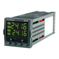
Eurotherm 2416
110 pages
Eurotherm 2500
224 pages
Eurotherm Mini8
343 pages
Eurotherm Nanodac
410 pages
Eurotherm 902 Series
157 pages
Eurotherm 7000 Series
46 pages
Eurotherm Invensys 2408
138 pages