5
PMC-E FORCED DRAFT EVAPORATIVE CONDENSERS
The supporting I-beams should be level to within 1.5mm in 1m before setting the unit. Do not level
the unit by shimming between the bottom flange and the beams as this will not provide proper
longitudinal support.
NOTE: Consult the latest version of the IBC code for required steel support layout and structural
design.
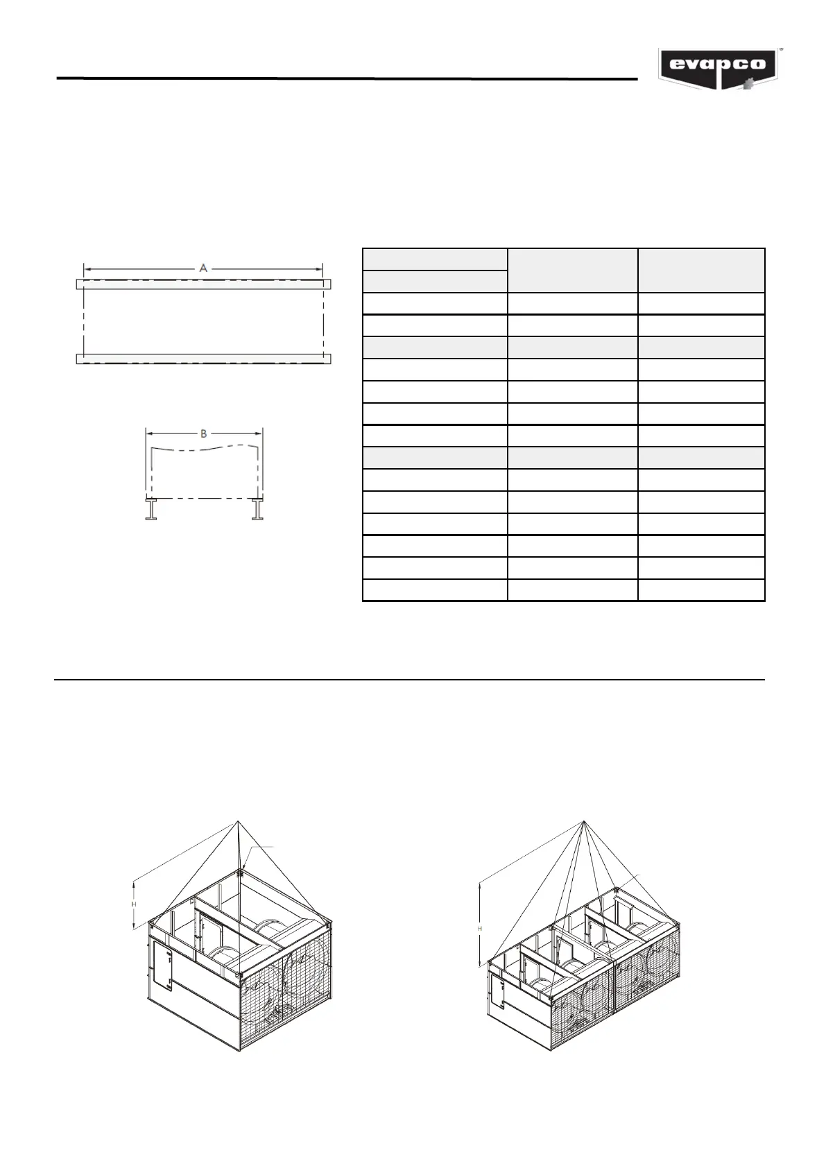
Table 1 – Steel Support Dimensions
Box Size (m)
A (mm) B (mm)
1.5m Wide Models
1.5 x 3.6 3648 1930
1.5 x 5.4 5490 1930
3m Wide Models A (mm) B (mm)
3 x 3.6 3651 2991
3 x 5.4 5490 2991
3 x 7.2 7337 2991
3 x 11 11024 2991
3.6m Wide Models A (mm) B (mm)
3.6 x 3.6 3651 3616
3.6 x 5.4 5490 3616
3.6 x 6 6102 3616
3.6 x 7.2 7337 3616
3.6 x 11 11024 3616
3.6 x 12.2 12243 3616
Plan View
End Elevation
Figure 1 – Structural Steel Support
(See Table 2 for model numbers corresponding to box size)
Rigging the Basin/Fan Section — Standard Lift
U-bolts or similar lifting points are located in the basin/fan section for lifting and final positioning
purposes as shown below in Figures 2 and 3. Units with lengths up to 6m have 4 total lift points.
Units with lengths over 6m long units have either 6 or 8 lift points. See Table 2 for the minimum
“H” dimensions for rigging the basin/fan assembly. Always use safety slings for extended lifts or
where any hazard exits. See the “Extended Lifts” section in this bulletin.
NOTE: Use all of the U-bolts or lift points provided for lifting.
LIFTING
U-BOLTS
LIFTING
U-BOLTS
Figure 2 – Basin/Fan Section (up to 6m Long) Figure 3 – Basin/Fan Section (Over 6m Long)