6
PMC-E FORCED DRAFT EVAPORATIVE CONDENSERS
Box Size (m) Model Numbers “H” Dimensions (m)
1.5m Wide Models
1.5 x 3.6 PMC-175E to 240E 3.6
1.5 x 5.4 PMC-250E to 375E 5.2
3m Wide Models
3 x 3.6 PMC-332E to 530E 4.3
3 x 5.4 PMC-503E to 792E 5.4
3 x 7.2 PMC-725E to 1056E 7
3 x 11 PMC-1006E to 1586E 10
3.6m Wide Models
3.6 x 3.6 PMC-376E to 640E 4.6
3.6 x 5.4 PMC-568E to 955E 5.8
3.6 x 6 PMC-715E to 1013E 6
3.6 x 7.2* PMC-752E to 1286E 7
3.6 x 11 PMC-1137E to 1911E 10
3.6 x 12.2 PMC-1705E to 2019E 11
Table 2 – Minimum “H” Dimension for the Basin/Fan Section Rigging (Standard Lift)
* This box size has two 3.6m long coil sections
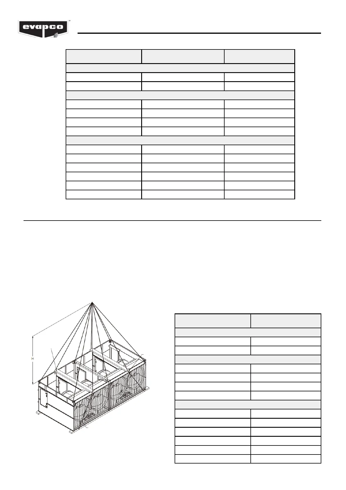
Rigging the Basin & Fan Section — Extended Lift
The recommended method for extended lifts is to use slings under the unit as shown in Figure 4.
Spreader bars should always be used between the cables at the top of the section to prevent damage
to the upper flanges. See Table 3 for the minimum “H” dimensions for rigging the basin/fan
assembly.
NOTE: The U-bolts or other lifting points should be used for final positioning only and for lifting
where no danger exists. If they are used for extended lifts, safety slings and spreader bars
should be provided under the sections as shown.
Safety slings, spreaders, and skids should be removed before final positioning of the unit.
Box Size (m) “H” Dimensions (m)
1.5m Wide Models
1.5 x 3.6 3.6
1.5 x 5.4 5.2
3m Wide Models
3 x 3.6 4.3
3 x 5.4 5.4
3 x 7.2 7
3 x 11 10
3.6m Wide Models
3.6 x 3.6 4.6
3.6 x 5.4 5.8
3.6 x 6 6
3.6 x 7.2* 7
3.6 x 11 10
3.6 x 12.2 11
Table 3 – Minimum “H” Dimension for the Basin/Fan
Section Rigging (Extended Lift)
(See Table 2 for model numbers corresponding to box size)
76mm X 200mm
SPREADERS
SAFETY
SLING
SAFETY SLING
Figure 4 – Proper Rigging Method for Extended Lifts