7
PMC-E FORCED DRAFT EVAPORATIVE CONDENSERS
Applying Sealer Tape
Once the bottom section has been set on the supporting steel and bolted in place, wipe the top
flanges to remove any dirt or moisture. Place sealer tape over the mounting hole centerline on the
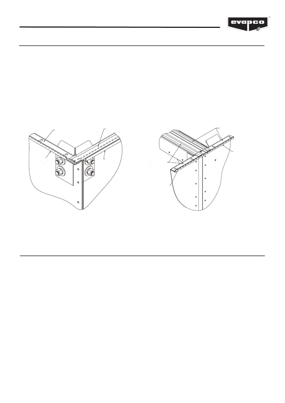
side flanges. Apply two strips of sealer tape, one partially overlapping the other, on the end
flanges. (NOTE: Sealer tape is applied completely around the perimeter of the section.)
The sealer tape should overlap on the corners as shown in Figure 5. Do not splice the sealer tape
along the end flanges and preferably not on the side flanges if it can be avoided. Always remove the
paper backing from the sealer tape.
For units which have two or more coil sections, sealer tape must be applied to all internal flanges
(Figure 6).
SEALER TAPE
SEALER TAPE
SEALER TAPE
SEALER TAPE
SIDE FLANGE
SIDE
FLANGE
SIDE FLANGE
END
FLANGE
Figure 5 – Proper Sealer Tape Application
Figure 6 – Sealer Detail for Center Joint of Units
with Two or More Coil Sections
Rigging the Coil Section
U-bolts or lift points are located inside the casing on the four corners of the coil for small single coil
sections. These lift points are for lifting and final positioning (Figure 7). On larger coil sections, the
lifting points are on the outside of the casing section (Figures 8 and 9).
The end and center eliminator sections on small, single coil sections should be removed before lifting
from the U-bolts or lift points.
See Table 4 for the minimum “H” dimensions for rigging the coil section. Always use safety slings
for extended lifts or where any hazard exits. See the “Extended Lifts” section in this bulletin.
NOTE: Use all of the U-bolts or lift points provided for lifting.
CAUTION: On units shipped as two separate sections, do not assemble sections and attempt to
lift the entire unit. The U-bolts and lift points are designed to carry only the weight of their
individual section.