66
Electrical System
Dash LT
Activates the lights above the helm area.
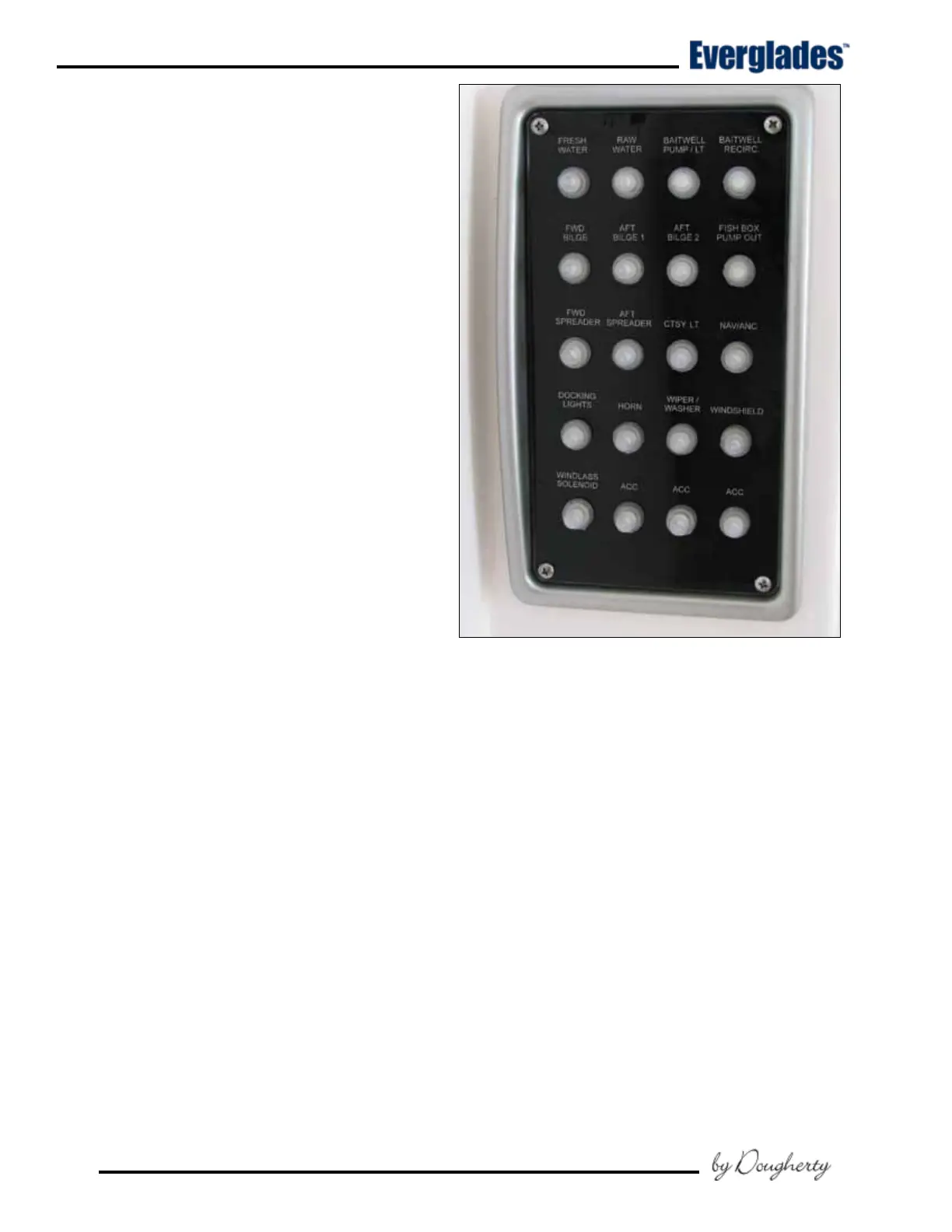
Hardtop Light CTSY LT
A three position switch that actives the overhead
lights in the in the Hardtop liner. The center po-
sition is OFF. Moving the switch in one direction
will activate the white overhead lights. Moving
the switch in the opposite direction activates the
blue overhead lights.
Blue lights have less effect on night vision
and should be selected if you need to illumi-
nate the helm area while navigating at night.
Deck Courtesy Lights
Activates the cockpit lighting. Move the switch in
one direction to activate white lights. Move the
switch in the opposite direction to activate blue
lights.
Nav/Anc
The switch is a three-position switch. The middle
position is OFF. Moving the switch in one direc-
tion will activate the navigation lights. Moving
the switch in the opposite direction activates the
anchor light.
Underwater Lights (Optional)
Activates the lights in the transom below the
waterline.
Additional DC Switches and Panels
Trim Tab Switch
Located in the helm. This switch controls the trim
tab planes located on the transom of the boat.
It is protected by a circuit breaker located in the
cabin DC breaker panel. Please refer to the Helm
Control Systems chapter for detailed information
on the operation of the trim tab controls.
Engine Trim and Tilt Switches
Located in the helm. These switches are typi-
cally installed in the engine throttle and shift
controls. They control the trimming and tilting
of the engines. Please refer to the Helm Control
Systems chapter and the engine owner’s manual
for information regarding the proper use of the
tilt and trim switches.
Waste Discharge Switch
A key activated momentary switch located in the
head compartment that controls the overboard
discharge pump system for the holding tank and
marine head system. Monitor the waste level in
the tank while pumping and turn the waste dis-
charge switch OFF immediately when pumping is
complete.
The key must be removed from the switch when-
ever the discharge pump is not being operated.
DC Circuit Breaker Panel
Power is distributed to most of the 12 volt acces-
sories through individual “push to reset” circuit
breakers located in the DC circuit breaker panel
in the head compartment. A main circuit breaker
located in the systems compartment protects the
system from an overload. Some 12 volt acces-
sories are operated directly by the circuit breaker
in the panel. Switches fed by the panel breakers
activate other accessories.
Head Compartment DC Circuit Breaker Panel


 To Next Page