63
Electrical System
6.4 DC System Switch
and Circuit Breaker Panels
Ignition Switch Panels
Ignition switch panels are unique to each engine
manufacturer and the engine control options
selected. Your dealer will provide you with the
proper starting procedure for your boat at the time
of delivery. Additional information for the ignition
switch system installed in your boat is located in
the engine and control system operating manuals
included in your information packet.
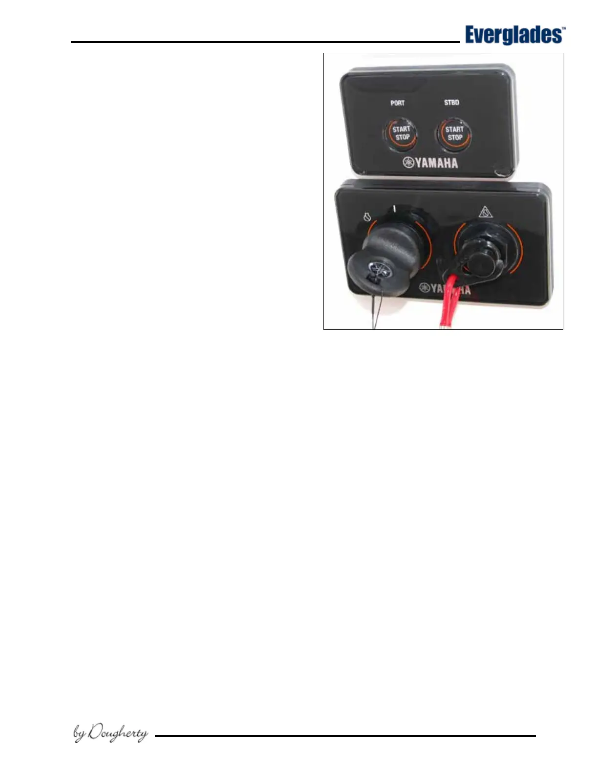
Yamaha Command Link Plus
®
Ignition
Most Everglades boats are equipped with Yamaha
engines and the Command Link Plus
®
ignition key
panels that offer the latest in technology and du-
rability. For twin engine installations, these are
“key” panels; which energize the ignition system
of multiple outboards with only one key.
The Start/Stop panel is used in conjunction with
the key panel and features lights which indicate
when outboards are running and a start/stop but-
ton for each engine. This system greatly simplies
the starting and stopping process of your engines.
For convenience and protection, engines can not
be restarted while running.
Starting procedure
Make sure the engines are down with the shift
lever in the neutral position and your hand is on
the control lever. Turn the ignition key to the ON
position to activate the start button for both en-
gines. Press and release the Start/Stop button for
the port engine. The computer will automatically
check all engine systems and start the engine.
When the engine stabilizes, repeat the starting
procedure for the starboard engine. Stop the
engines by pressing the start/stop buttons again.
The engine ignition circuits are protected by fuses
or circuit breakers located on each engine.
12 volt Helm Accessory Switch Panel
The main accessory switch panel is located at the
helm. Most of the circuit breakers that protect
the accessories are located in the head compart-
ment DC panel. An LED light built into the toggle
switches indicates that the circuit is activated.
The following is a description of the accesso-
ries controlled by the main accessory switch
panel:
Typical Yamaha Command Link Ignition
and Engine Start/Stop Switch System
Fresh Water
Activates the fresh water pump that supplies
the fresh water washdown hose connector in the
cockpit, windshield washer, marine toilet and the
head sink and shower. The pump is the pressure
demand type. A pressure switch automatically
controls the water pump when the system is ac-
tivated and properly primed.
Raw Water
Activates the raw water washdown pump that
supplies the raw washdown hose connector in
the cockpit. The pump is the pressure demand
type. A pressure switch automatically controls
the water pump when the system is activated and
properly primed.
Windlass
This switch controls the windlass which is mounted
to the deck above the rope locker. It is protected
by a circuit breaker of the type and rating rec-
ommended by the windlass manufacturer that is
located near the battery switches. Another circuit
breaker on the DC panel protects the circuit for
the windlass switch.