71
Electrical System
CAUTION
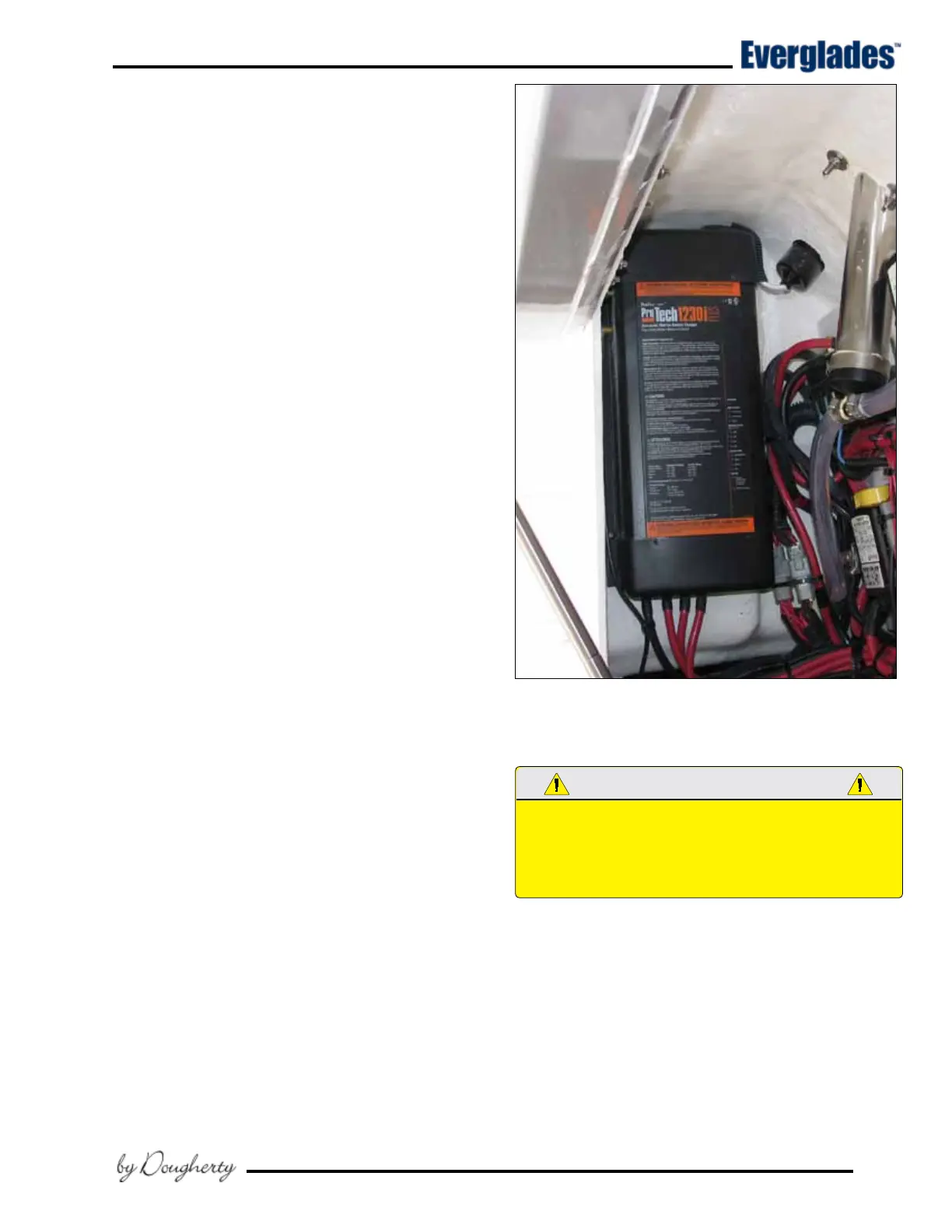
Battery Charger Operation
AC electrical current is supplied directly to the
automatic battery charger, located in the systems
compartment, by the shore power cord and AC
inlet plug near the transom door. The battery
charger will charge and maintain the 12 volt bat-
teries simultaneously when activated. It is fully
automatic.
The wires that supply DC charging current to the
batteries are protected by internal fuses in the bat-
tery charger and inline fuses, one for each battery
output wire, near each battery. The inline fuses
protect the DC charging circuit from the batteries
to the charger. The internal fuses in the charger
protect the DC charging circuit from the charger to
the batteries. Refer to the battery charger owner’s
manual for more information on the features and
operation of the battery charger.
The charge to the engine batteries can be moni-
tored by using the volt meters in the engine gauge
display or the LED lights on the charger. To moni-
tor the engine batteries with the volt meters in
the engine gauge display, activate the charger
and turn the engine battery switches on. Turn
the ignition key switch for each engine to the ON
position (DO NOT START THE ENGINES) and read
the voltage on the volt meter for each engine. If
the batteries are in good condition and charging
properly, the volt meters will indicate between 12
and 14.5 volts. If the reading is below 12 volts,
then the battery is not accepting a charge or the
charger is not working properly. Always turn the
ignition switches off immediately after the moni-
toring is complete when using the voltmeters in
the engine gauge cluster.
6.7 Electrical System Maintenance
DC Electrical System Maintenance
At least once a year, spray all exposed electrical
components behind the helm, in the transom area
and in the plugs with a protector. Exterior light
xture bulbs should be removed and the metal
contact areas coated with a non-water soluble lu-
bricant like Teon or Silicone grease. The sockets
should be sprayed with a protector. Care must
be taken not to get any oil or grease on the glass
portion of the bulbs as this will cause the bulb to
overheat and burn out. LED lights are sealed and
not serviceable.
Typical Battery Charger
WHEN REPLACING LIGHT bULbS IN MARINE LIGHT FIxTURES,
ALWAYS USE A bULb WITH THE SAME RATING AS THE
ORIGINAL. USING A DIFFERENT bULb COULD CAUSE THE
FIxTURE TO OVERHEAT AND MELT OR SHORT CIRCUIT.
Check all below deck wiring to be sure it is prop-
erly supported, that the insulation is sound and
that there are no loose or corroded terminals.
Corroded terminals should be thoroughly cleaned
with sandpaper or replaced, tightened securely
and sprayed with a metal and electrical protector.
Inspect all engine wiring.