68
Electrical System
Notice:
If a main circuit breaker trips, always make
sure the problem that caused the breaker to
trip is found and corrected before resetting
the breaker.
The following are the main circuits supplied
and protected by heavy duty circuit breakers:
Main
Protects the circuit that supplies 12 volt current
to the head compartment DC breaker Panel. This
circuit is deactivated when the House battery
switch is off.
Electronics
Protects the main circuit that supplies 12 volt
current to the electronics fuse panel in the helm.
This circuit is deactivated when the House bat-
tery switch is off.
Windshield
Protects the circuit that supplies 12 volt current
to the hydraulic system that raises and lowers the
windshield. This circuit is deactivated when the
House battery switch is off.
Power Steering (Optional)
Protects the circuit that supplies 12 volt current to
the hydraulic steering assist system. This circuit is
deactivated when the House battery switch is off.
Windlass
Protects the circuit that supplies 12 volt current
to the windlass main circuit. This circuit is de-
activated when the House battery switch is off.
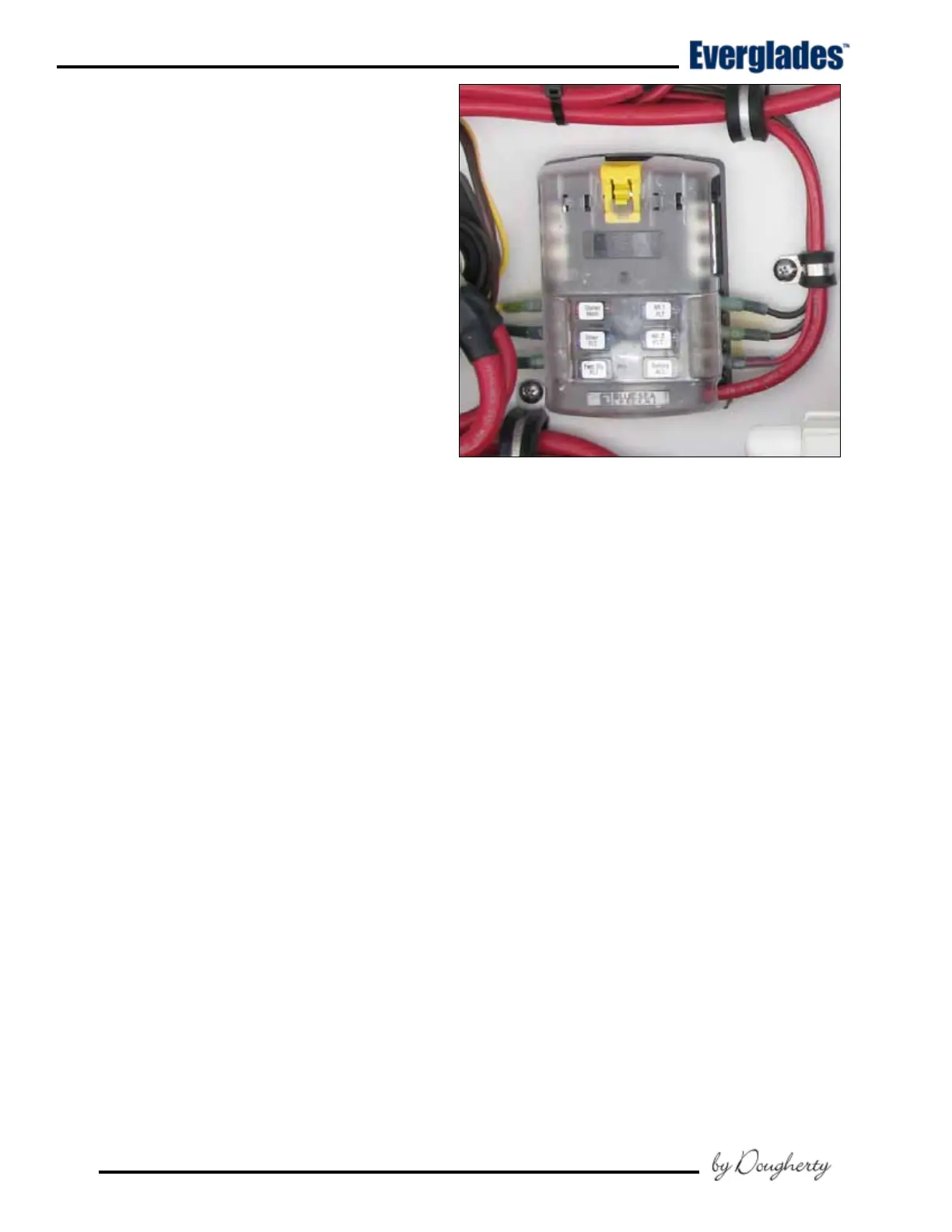
Continuous Power Fuse Panel
Located near the battery switches. The fuses in
the panel protect the circuits that are always ac-
tive not turned off by the battery switches. The
continuous power circuits are always supplied
current when the House batteries are connected.
The fuses in this panel provide continuous
power and protect the circuits for the fol-
lowing accessories:
Stereo Memory
Protects the circuit that supplies continuous 12
volt electrical current to the memory circuit in
the stereo.
Continuos Power Fuse Panel
Shower FLT
Protects the circuit for sump pump for the head
compartment and shower drain. The sump is fully
automatic and is accessed through a hatch in the
head compartment sole.
Fwd Blg FLT
Protects the circuit for the automatic switch that
activates the bilge pump located in the bilge below
the head compartment. The pump and switch
are accessed through a hatch below the head
compartment sole. A red light in the Forward
Bilge Pump switch will be lit whenever the pump
is activated.
Aft 1 FLT
Protects the circuit for the automatic switch that
activates the mid stern bilge pump located in the
bilge below the systems compartment. A red light
in the Aft 2 Bilge Pump switch will be lit whenever
the pump is activated.
Aft 2 FLT
Protects the circuit for the automatic switch that
activates the stern bilge pump located in the
bilge near the transom. A red light in the Aft 1
Bilge Pump switch will be lit whenever the pump
is activated.


 To Next Page