14 Installation Instructions
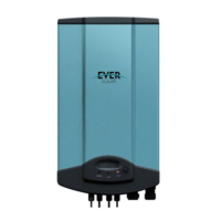
After remove the ornamental plate and connection cover, the plug connectors show
above.
Object Description
1 DC input: Plug connectors for connecting the PV modules. Their polarity
is positive, negative, negative and positive terminals, respectively, which
are signed in the front of the inverter.
2 Communication connecting area. Eversol inverters are configured with
RS485 interface as standard, and users can change it to RS232 interface.
3 Terminal for grid connection (AC output). They are signed by A, B and C,
respectively. When wiring please note that, A is corresponding to N wire,
B is corresponding to L wire, and C is to PE wire.
Notes:
1. After the inverter has been installed in its fixed position, the
electrical connection to the unit can be established.
2. Make sure Max. Open Voltage and short-circuit current of the
PV string accord with the Spec.
3. Choose the appropriate cable width for AC / DC wire (AWG12, 2.5 mm
2
).
4. To connect the inverter, the AC and DC side must be disconnected from all
power sources and secured against being inadvertently switched back on.
5. Before connecting inverter to PV modules and public grid, please make sure the
polarity is correct.
5.3.1 Connection to the public grid (AC)
!Attention
You must safeguard each inverter with an individual breaker in
order that the inverter can be safely disconnected under load.
There are two different AC connectors. Whatever which one you get, please connect
AC wires with the inverter via it obey the procedures below: