10
www.evolutionrage.com
11
www.evolutionrage.com
GETTING STARTED WARNING: Always disconnect the saw from the
power source before making adjustments.
Refer to the “Service Parts Diagram”. Install a blade
as detailed in the “Installing or Removing a Blade”
section.
WARNING: Never start the saw with the cutting
edge of the saw blade in contact with the workpiece
surface. Do not retract blade guard manually. Guard
retracts automatically.
This saw is equipped with an approved cord and
plug for its intended Country of use. Do not alter or
modify the power cord.
Installing or Removing a Blade
WARNING: Only use genuine Evolution blades
which are designed for this machine. Ensure that
the maximum speed of the blade is compatible with
the machine. Only perform this operation with the
machine disconnected from the power supply.
Note: It is recommended that the operator
considers wearing protective gloves when handling
the blade during installation or when changing the
machines blade.
1. Place saw on a level, secure surface.
2. Remove the chip collector from the machine by
undoing the (2) large thumb screws. (Fig. 1)
Note: The chip collector thumb screws are ‘captive’
and cannot be removed from the machine.
3. Lock the machine arbor by engaging the arbor
lock. (Fig. 2)
4. Using the supplied Allen Key loosen and remove
the arbor socket headed screw and outer blade
drive ange. (Fig. 3)
5. Remove the saw blade.
6. Thoroughly clean inner and outer blade drive
anges and blade mounting surface before
installing a new blade.
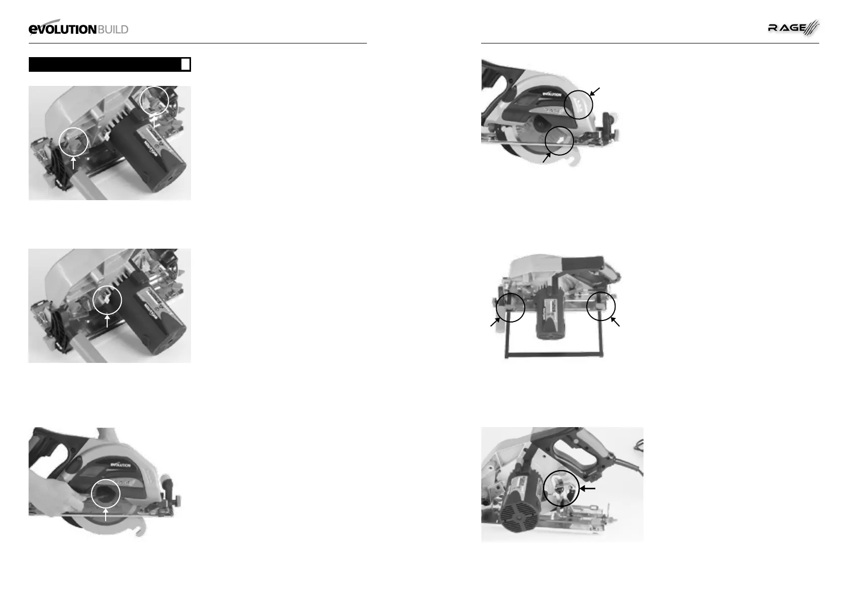
7. Ensure that the direction of rotation arrows
printed on the blade, match the direction of rotation
arrow found on the chip collection cover. (Fig. 4)
8. Reinstall the outer drive ange and the arbor
socket headed screw.
9. Engage the arbor lock and tighten the arbor
socket headed screw securely using the Allen key.
Note : The socket headed arbor screw has a RH
thread.
10. Replace the chip collector and securely tighten
the two thumb screws.
11. Check that the arbor lock is fully released by
manually rotating the blade.
12. Check the operation of the safety guard.
Parallel Edge Guide
A parallel guide (for help when rip cutting) can be
tted to the sole plate of the machine The guides
arms should be inserted into the rectangular slots in
the turned up edges of the sole plate, and slid under
the locking thumb screws. (Fig. 5)
Note: The edge guide can be tted to either side
of the sole plate and should only be tted and
adjusted with the machine disconnected from the
power supply.
Adjust the edge guide so that it is at the required
distance from the blade and tighten the two thumb
screws. Check that the edge guide is parallel to the
saw blade.
Adjustment of the Cutting Depth
Release the Lever Lock to adjust to the required cutting
depth. In most cases depth should be set at maximum
unless there are obstructions below the work surface.
Tighten the Lever Lock securely to lock in the required
position. (Fig. 6)
Adjustment of the Cutting Angle
1. Loosen the Bevel Locking Screw found at the
front of the saw.
2. Loosen the Rear Bevel Locking Screw found at
the rear of the machines sole plate.
3. Tilt the blade to the required angle. (Fig. 7)
4. Tighten both Bevel Locking Screws securely
Note: An angle scale (0
O
-45
O
) is incorporated into
the Bevel Locking quadrant to aid setting.
Operating Advice
Carry out routine safety checks each time you
use the machine. Check that all safety guards are
operating correctly, and that all adjustment handles/
screws are tightened securely.
Check that the blade is secure and installed
correctly. Also check that it is the correct blade for
the material being cut.
Check the integrity of the power cord.
Always clamp the workpiece to a rigid support such
as a bench or saw horse whenever possible.
GETTING STARTED
GB
FIG 1
FIG 2
FIG 3
FIG 4
FIG 5
FIG 6