12
www.evolutionpowertools.com
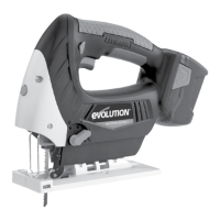
Fig 3 (b)
Close up view
of Rotary Control.
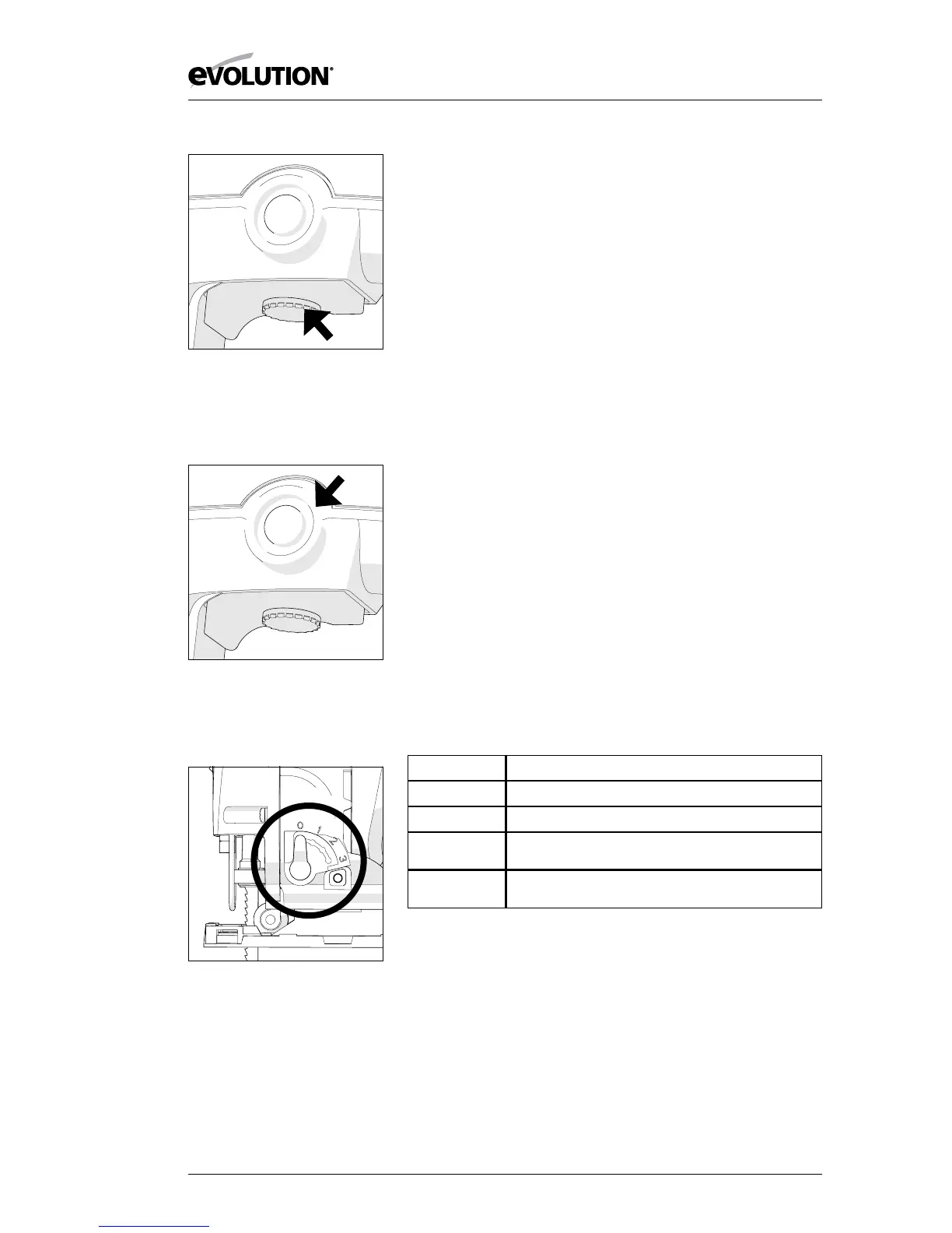
Fig 3 (c)
Close up view of
Locking Button.
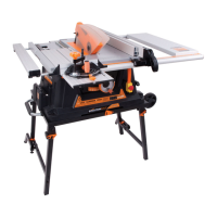
Fig 4
Close up view of
Selection Switch Lever.
3. TRIGGER SWITCH LOCKING BUTTON (Fig. 3c)
• Pullthetriggerfullyandrotatetherotarycontroluntilthe
desired speed is obtained.
• Pushinthespeedlockingbuttontolockthetriggeratthe
selected speed.
• Pressthetriggerswitchgentlyandthenreleasetodisengage
the selected speed and to switch the machine o.
4. CUTTING ACTION SELECTION SWITCH (Fig. 4)
This jigsaw has a 4 position switch (0-3) located on the Left
Hand side of the machine just behind the blade. Only operate
this switch when the machine is switched ‘O’ and the blade is
stationary.
Position ‘0’ Straight cutting action
Positions ‘1 – 3’ Orbital cutting actions
Orbital cutting action has an aggressive blade cutting motion
and is especially suited for cutting soft materials.
During orbital cutting the blade moves forwards as well as
up and down. Position 1 is the least aggressive of the orbital
cutting actions, with position 3 being the most aggressive.
The Table below gives some typical examples of the use of the
orbital cutting facility. We recommend that the operator always
practices on a piece of unwanted material to determine the
most suitable selection for the task at hand.
POSITION TYPICAL APPLICATION
0 Thin materials. Fine cuts. Tight curves. All metals.
1 Hard materials such as chipboard, MDF, Plywood etc.
2 Thick materials such as constructional timber and
plastic.
3 Fast cuts when cutting with the grain in softwood
material.