14
www.evolutionpowertools.com
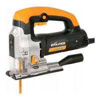
Fig 8
Close up view of socket
headed screw.
• Loosenthesocketheadedscrewthatholdsthefootplateto
the machine. (Fig. 8)
• Tiltthefootplatetothedesiredangle.Toengageoneof
the positive stops it will be necessary to slide the footplate
backwards or forwards depending upon the stop required.
• Tightenthesocket-headedscrewcarefullysoasnotto
damage the threads.
• Re-installtheDustExtractionAdaptortube.
• Rettheplasticfootplateshoeensuringthatallsix(6)
securing lugs (2 to the front of the footplate and 2 either side)
are correctly seated.
Note: The positive location stops are intended as a guide only.
For accurate setting of the footplate we recommend the use of a
vernier angle gauge (not supplied).
7. CHIP GUARDS
Two (2) plastic chip guards are provided. The Front Chip Guard
should always be tted and the Footplate Chip Guard can be
tted to the machine as and when required.
To t the Front Chip Guard:
• Ensurethatthemachineisdisconnectedfromthepowersupply
• Thefrontguard(Fig. 9) clips over the front of the machine,
below the laser guide and in front of the steel blade guard.
Note: This guard is precisely engineered and designed to just
clip into place. There is sucient ‘spring’ in the design to allow
the guard to be carefully positioned into its service position.
The operator should use care and ensure that the guard is not
‘forced’ into place with the attendant risk of damage to the
guard. Seat the guard carefully in its service position.
The Footplate Chip Guard (Fig. 10) can be useful when cutting
long straight lines. The use of this guard will help prevent the
sawblade from swinging during a cut.
To t the Footplate Chip Guard:
• Ensurethatthemachineisdisconnectedfromthepowersupply.
• UncliptheplasticFootplateShoefromtheFootplate.
• CliptheFootplateChipGuardintotheinsideoftheFootplate
Shoe with the ‘Vee’ pointing towards the rear of the shoe, and
the raised platform positioned within the throat of the shoe.
Ensure positive location within the shoe. The guard should lie
‘ush’ with both surfaces of the shoe.
• CarefullyreplacetheFootplateShoewiththeattachedChip
Guard onto the Footplate.
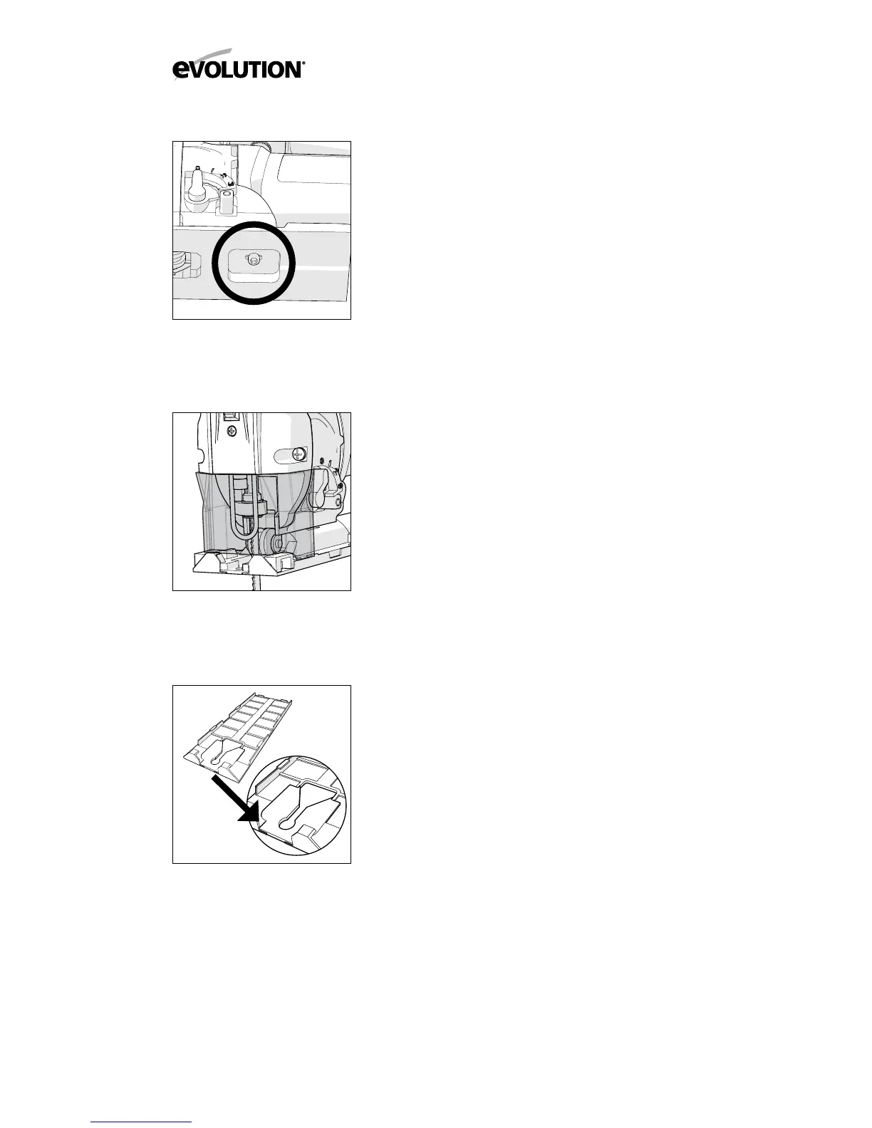
Fig 9
Close up view of Front
Guard in service position.
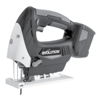
Fig 10
Close up view of Footplate
Guard in service position
before installation of
footplate shoe.