Do you have a question about the Evoqua DEPOLOX 400 M and is the answer not in the manual?
Identifies intended users for the manual.
Explains the manual's organization and purpose.
Details symbols and notes used for safety and information.
Specifies approved applications and limitations of the DEPOLOX 400 M.
Outlines critical safety precautions and personnel qualifications.
Lists safety rules for different operational states and procedures.
Details requirements for maintaining warranty validity.
Clarifies manufacturer's liability limitations for installation and use.
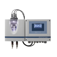
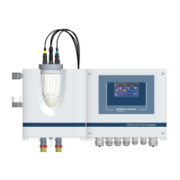
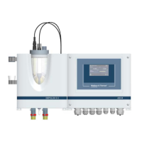
Provides an overview of the DEPOLOX 400 M's modular design.
Lists available module and sensor versions with part numbers.
Shows compatibility of flow cells, assemblies, and sensors.
Details measuring principles and applications of various sensors.
Lists available accessories for enhanced functionality.
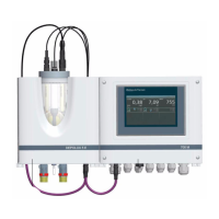
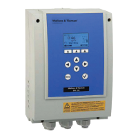
Describes the design, functions, and features of the electronics module.
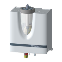
Explains the design and function of the DEPOLOX 5 C flow cell.
Details the design and function of the VariaSens C flow cell.
Covers the design and function of the Y-style flow-through assembly.
Introduces various sensor types and their technical specifications.
Presents detailed technical specifications for modules and components.
Details firmware updates and data logging via USB.
Explains data transfer for higher-level control systems.
Describes network connectivity for visualization and data communication.
Covers data exchange using the Modbus TCP protocol.
Lists all items included in the product package.
Provides guidelines for safe handling and storage of the equipment.
Specifies environmental requirements for safe and correct operation.
Outlines general mechanical installation precautions and requirements.
Details procedures for mounting the electronics module and flow cell.
Instructions for accessing internal components by removing covers.
Guide for fitting the optional strainer for water purification.
Specifies how to connect the sample water inlet for accurate measurements.
Instructions for connecting the sample water outlet.
Steps to prepare the DEPOLOX 5 C flow cell before operation.
Steps to prepare the VariaSens C flow cell before operation.
Guidance on installing various sensors into flow cells.
Instructions for connecting sensor cables to the electronics module.
Covers electrical connection requirements and safety.
Steps for initial setup and configuration after installation.
Overview of the touchscreen interface and navigation symbols.
Describes how to view and adjust measurement settings.
Accesses configuration settings like operation mode, calibration, and alarms.
How to access and use the device's web interface for monitoring.
Procedure for updating the device's firmware via USB.
Details the process for calibrating sensors to ensure accuracy.
Explains how to interpret and manage device messages and alarms.
Troubleshooting guide for common device issues.
Setting up automated reminders for maintenance tasks.
Lists recommended maintenance schedules for various components.
Lists part numbers for maintenance kits for flow cells.
Procedure for daily inspection of flow cell for leaks.
Maintenance procedures specific to the DEPOLOX 5 C flow cell.
Steps for cleaning or replacing the fine filter in VariaSens C.
Maintenance for flow rate monitor and check valve components.
How to clean or replace the optional strainer.
Instructions for replacing fuses on the electronics module.
Guide for replacing the real-time clock battery.
General cleaning recommendations for the device.
Lists spare parts for the 400 M electronics module.
Lists spare parts for the DEPOLOX 5 C flow cell (non-pressurized).
Lists spare parts for the DEPOLOX 5 C flow cell (pressurized).
Lists spare parts for the VariaSens C flow cell (non-pressurized).
Lists spare parts for the VariaSens C flow cell (pressurized).
Lists spare parts for the DEPOLOX 5 C flow cell body cover.
Lists spare parts for the VariaSens C flow cell body.
Lists spare parts for the Y-style flow-through assembly.
Lists sensors and related connection components.
Lists membrane sensors and their extension cables.
Lists various accessories for the DEPOLOX 400 M system.
Illustrates wiring connections for digital input signals.
Shows wiring for USB, Ethernet, and RS485 interfaces.
| Brand | Evoqua |
|---|---|
| Model | DEPOLOX 400 M |
| Category | Measuring Instruments |
| Language | English |