IONPURE
®
LX CEDI Modules
Page 21 IP-MAN-LX-1220-EN.pdf
5. START-UP PROCEDURE
5.1. Test Interlocks
· Test flow switches and other interlocks, including the RO interlock if applicable
· Test pressure relief if applicable
· Set alarm points
5.2. Startup of LX Modules
· Make sure that modules are correctly connected to the DC power source.
· Make sure that the LX product line is directed to drain.
· Turn on the feedwater. Adjust pump and/or valves to obtain the desired flows and
pressures in the product and reject streams. The reject flow is typically set at about
11% of the product flow (this gives a water recovery of 90%). See Section 5.4, below.
· Valves are adjusted so the product outlet pressure is about 2 to 5 psig (0.1 to 0.3 bar)
higher than the reject outlet pressure at the desired flow rates.
· Adjust the DC power supply to the current setting determined in section 4.2.
· Test all flow switches and interlocks to ensure LX DC power is shut off when flow is
interrupted.
· Continue to direct the product water to drain until it reaches the desired quality.
· Once product reaches the desired quality, connect to process. Readjust pressures as
required to maintain product outlet pressure 2 to 5 psi (0.1 to 0.3 bar) above the reject
outlet pressure.
· Record operating data daily on suitable log sheet (see example in section 7.0). The
CEDI system should achieve steady-state operation in a few days,
5.3. Minimum Reject Flow Rate
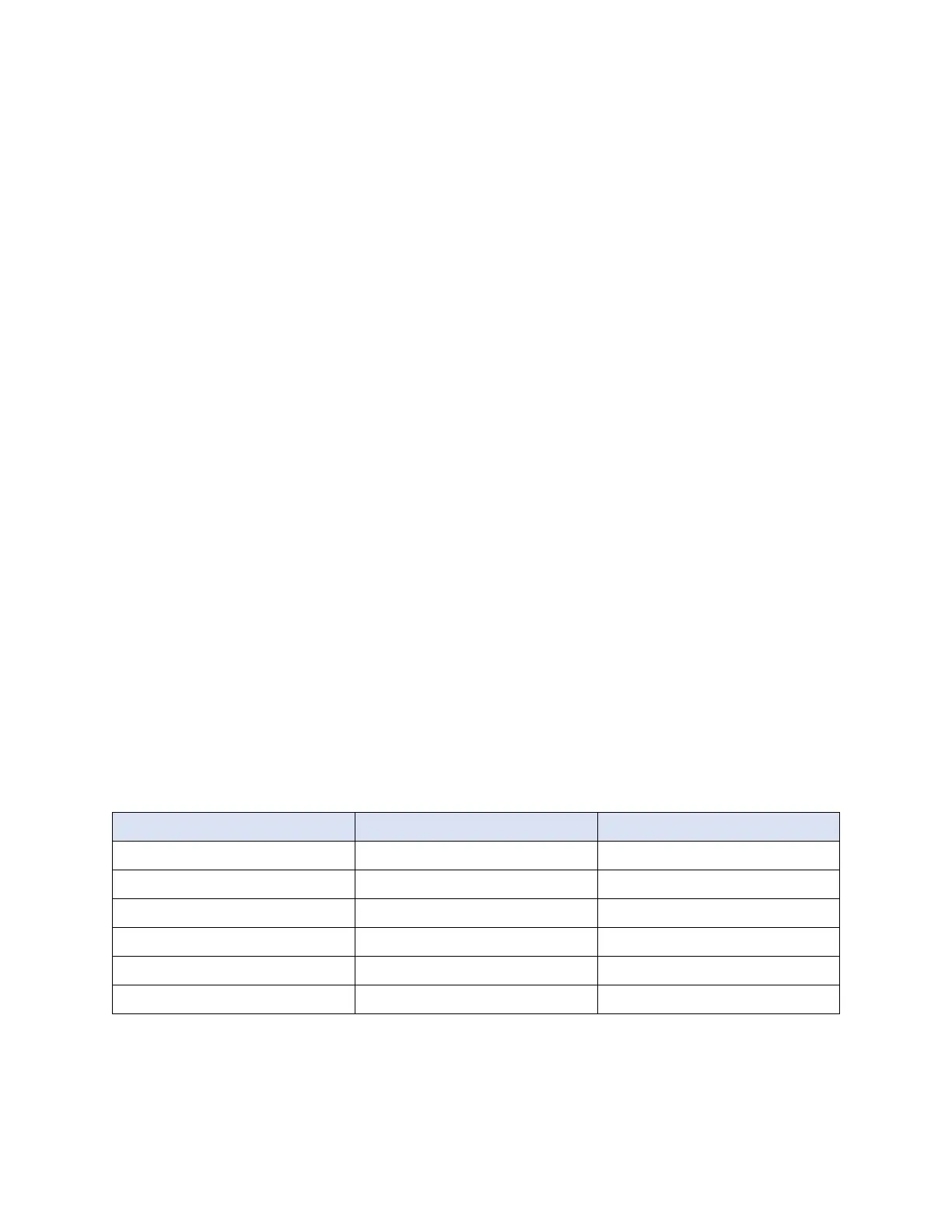
Table 5-1 Minimum Reject Flow Rates for Various LX Module Sizes
Module Size gpm L/min
IP-LXM 04 0.07 0.26
IP-LXM 10 0.16 0.61
IP-LXM 18 0.27 1.02
IP-LXM 24 0.36 1.36
IP-LXM 30 0.44 1.67
IP-LXM 45 0.66 2.50
5.4. Water Recovery
· Percent water recovery = (100)(product flow)/(product flow + reject flow)
 Loading...