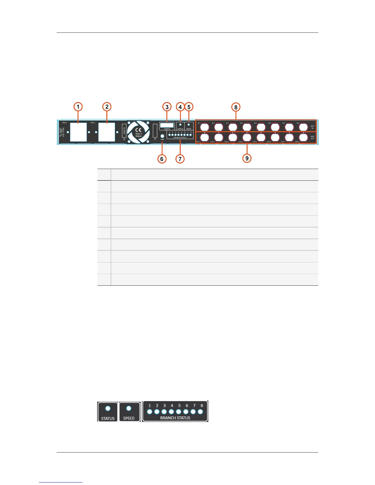
2.3. Rear Panel
Overview
# Element
1. Power supply 2 (IEC connector)
2. Power supply 1 (IEC connector)
3. Configuration DIP switch matrix
4. Status LED
5. Speed LED
6. Link connector
7. Branch status LEDs
8. Input connectors
9. Output connectors
Configuration DIP Switch Matrix
All 8 switches must be up for normal operations.
Link Connector
For EVS user only.
Status, Speed and Branch Status LEDs
Those LEDs match the corresponding front LEDs.
6 2. Hardware
EVS Broadcast Equipment SA Issue 4.00.B- June 2014
 Loading...