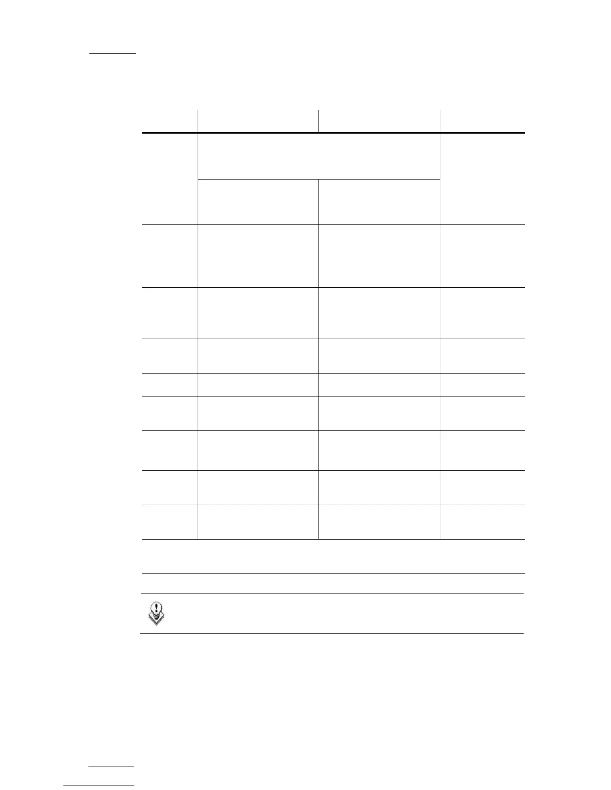
Connector Assignments in SD and HD Modes
Connector SD mode HD mode Connector label
J1 J5 is factory-wired to the backplane instead of J1.
You can connect J1 instead of J5 if monitoring
(CVBS or SDI) is required in SD or HD mode.
CHAR SD
SDI/CVBS (*)
monitoring output (SD)
SDI/CVBS(*) monitoring
output (SD, down-
converted)
J2 SDI monitoring output
(SD)
SDI monitoring output
(SD, down-converted)
Not wired to the
backplane.
Used for onboard
multiviewer input
J3 Loop-through for the SDI
input signal
(SD)
Loop-through for the SDI
input signal
(SD, down-converted)
OUT B
J4 SDI monitoring output
(SD)
SDI monitoring output
(HD/SD)
CHAR OUT
SD/HD
J5 N/A N/A IN B
J6 SDI program output
(SD)
HD SDI program output
(HD)
OUT
J7
SDI program output
(SD, identical to J6)
HD SDI program output
(HD, identical to J6)
OUT
J8 SDI input
(SD)
HD SDI input
(HD)
IN
J9 Alternate SDI input
(SD, for hardware loop)
Alternate HD SDI input
(HD, for hardware loop)
Used for loop in
* The switch between SDI and CVBS on J1 is done by a software setting in the EVS
Configuration menu.
Note
The loops of the input signal are not genlocked.


![Preview: EVS XT[2]](https://data.easymanua.ls/products/617905/200x200/evs-xt-2.webp)


