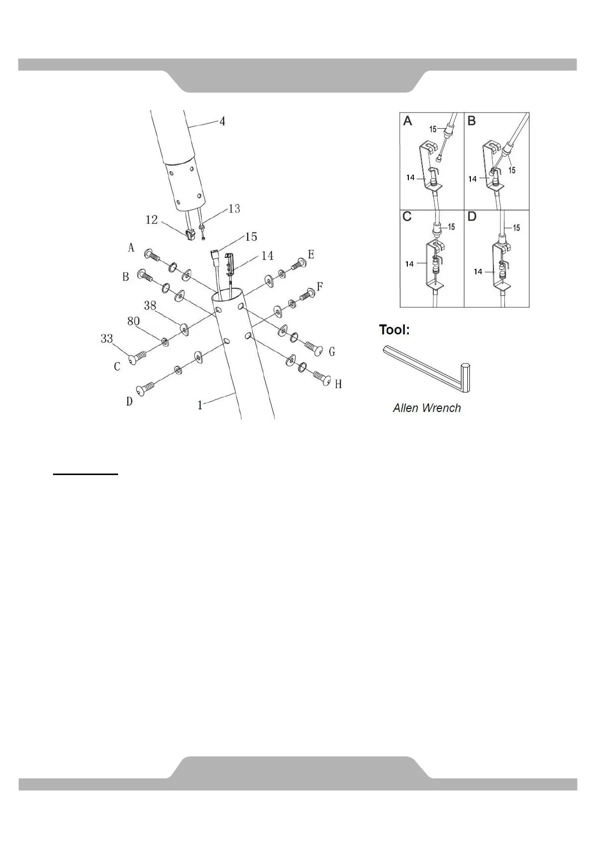
MUST TIGHTEN IN SEQUENCE: A,B,C,D,E,F,G,H.
5. Assemble Front Post.
Put the cable end of resistance cable of Tension Control Knob (13) into the cable lock of
Tension Cable (14), see Figure A. Pull the resistance cable of Tension Control Knob (13)
up and force it into the slot of metal bracket of Tension Cable (14), see Figure B. Insert the
metal fitting on the resistance cable of Tension Control Knob (13) into the hole at the end of
the slot in the metal bracket of Tension Cable (14), see Figure C. Connect the resistance
cable of Tension Control Knob (13) to Tension Cable (14) complete, see Figure D.
Use the Allen Wrench to remove eight Hexagon Socket Head Bolts (33), eight Spring
Washers (80), and eight Curve Washers (38) from the Front Post (4).
Connect the Computer Wire (12) from the Front Post (4) with the Extension Sensor Wire (15)
from the Main Frame (1). Insert the Front Post (4) into Main Frame (1). Make sure the
wire stay connected. Tighten the eight Hexagon Socket Head Bolts (33) which start with
A,B,C & D first, four Spring Washers (80), and four Curve Washers (38) by Allen Wrench,
then tighten E,F, G &H as same procedure.
 Loading...