Powerware
®
Plus 12 Operator's Manual (164200090 Rev E) 37
. Remove the two screws located at the top rear of the battery cabinet
(see Figure 9). Retain the screws.
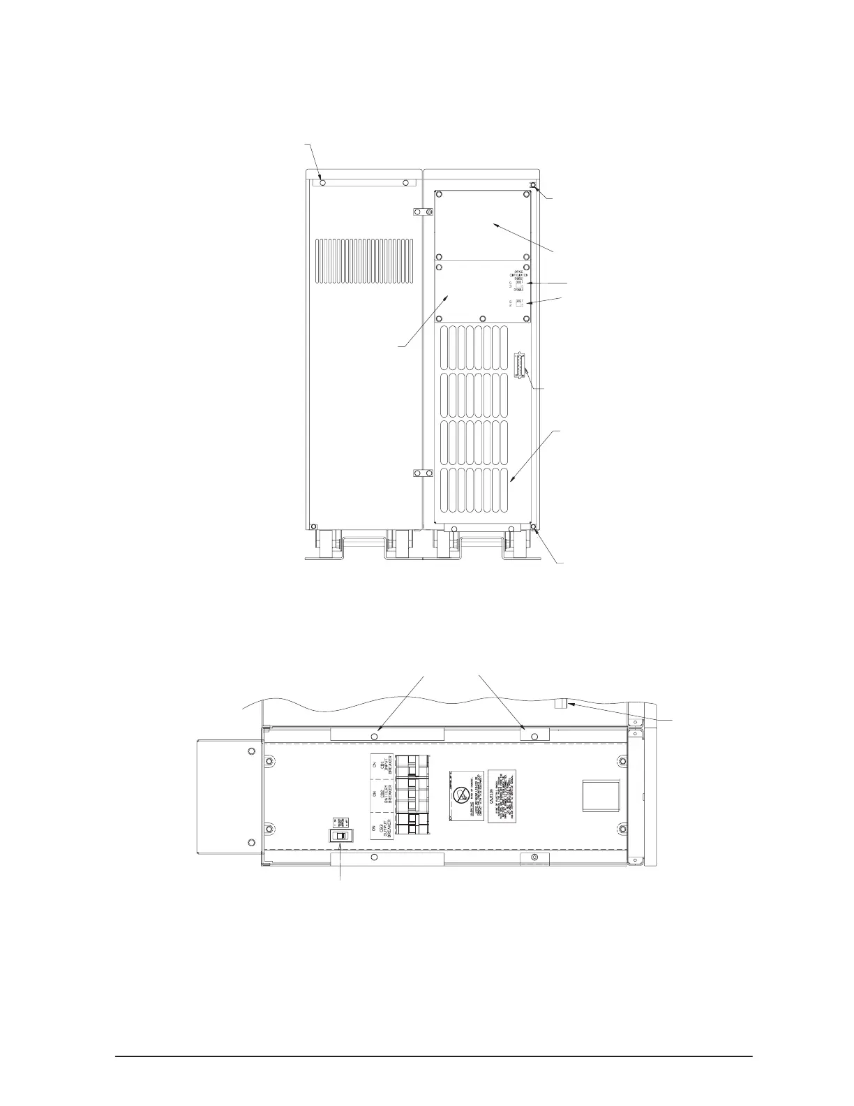
Right Side Cover Screws
Communications Port
Air Exhausts
Right Side Cover Screws
Input Neutral Configuration Switch
Removable
Conduit
Plate
Top Cover Screws
Battery Cabinet UPS Cabinet
Removable Power Termination
Block Plate
Bypass Configuration Switch
Figure 9. Rear View of the Plus 12 UPS
. Remove the top cover of the battery cabinet by pulling the top cover toward
the rear of the unit to release the spring latch and lift the cover off the cabinet.
Right Side Cover Screws
Battery
Spring
Latch
Maintenance Bypass Switch
Figure 10. Top View with UPS Cover Removed