Powerware
®
Plus 12 Operator's Manual (164200090 Rev E) 38
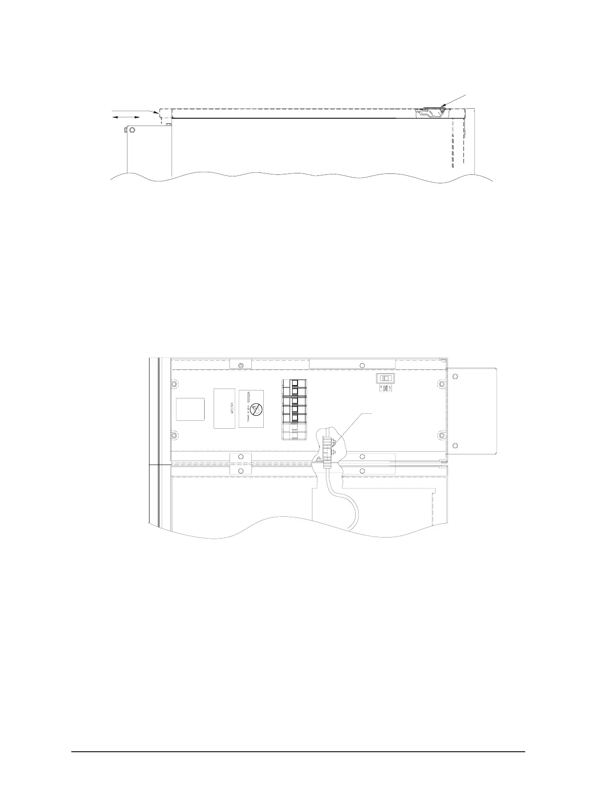
. Open the top cover of the UPS cabinet by sliding the cover latch forward and
lift up as shown in Figure 11.
UPS Cover Latch
Step 9
Figure 11. Removing the Top Cover from the UPS Cabinet
. Remove the right side cover of the UPS cabinet by removing the mounting
screws (four each) as shown in Figures 9 and 10.
. Pull the right side cover out from the top and then detach it from the system.
Retain the side cover and mounting hardware.
. Find the two interconnect cables secured to the top of the battery tray.
. Select either one of the cables. Cut the retaining straps.
. Connect the UPS to the first battery cabinet through the top cutout in the
battery cabinet (Figure 12).
1st Battery Cabinet
Interconnect
Cables
Figure 12. Connecting the UPS and Battery Cables (Top View)
. Mate the connector with the mating half located in the I/O module as shown in
Figure 13. If the cabinets are not permanently mounted to the floor, you can
slide them apart to make the connection.