8 Installation
Powerware
®
Plus 12 Operator's Manual (164200090 Rev E) 46
Installing the Power Distribution Module (optional)
The PDM provides customer receptacle options for singleĆ and threeĆphase
applications. The PDM also has a hardwire output panel for mixing hardware and
receptacle output configurations.
NOTE: The PDM cannot be installed on units with a 127/220V configuration.
Only qualified service personnel (such as a licensed electrician) should
perform the PDM installation. Risk of electrical shock.
To perform the PDM installation, you need the following tools: a 1/4I hexĆnut driver, a
small flatĆhead screwdriver, and a 1 3/8I wrench. Make sure that you read all of the
caution and warning statements in Safety Considerations" beginning on page before
performing the installation.
The following instructions assume you have already installed the UPS and battery
cabinets according to the procedure in Installing the UPS and Battery Cabinets" on
page 34.
The critical load is deĆenergized during the PDM cabinet installation.
Make sure your UPS is shut down before performing any steps in this section
(see page 23).
Use the following procedure to install the PDM:
. Open the top cover of the UPS and make sure that all breakers (input, output,
and battery) are in the OFF (O) position.
. If output is already connected to your unit, disconnect all output connections
from the terminals on the UPS rear panel (see Figure 22 of page 47).
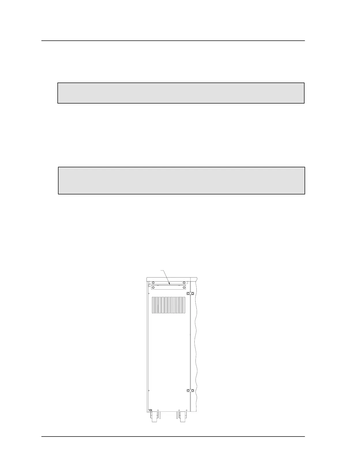
. Using the two hex screws provided in the hardware kit, install the PDM
mounting bracket to the rear panel of the battery cabinet (see Figure 21).
PDM Mounting Bracket
Figure 21. Battery Cabinet with PDM (Rear View)