EasyManua.ls Logo

Exlar Tritex II DC Series - User Manual

Exlar Tritex II DC Series
70 pages
Print Icon
To Next Page IconTo Next Page
Loading...
Curtiss-Wright | Tritex II DC Rev. J PN49220 2/8/2016
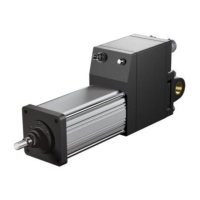
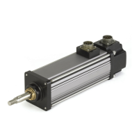
1
Tritex II DC Series Actuators
Models TDM/TDX 060 & 075, RDM/RDG 060, 075 & 090
48 VDC Linear and Rotary Actuator
Installation and Service Manual
Information furnished by Exlar Corporation is believed to be accurate and reliable.
However, no responsibility is assumed by Exlar Corporation for its use. Exlar reserves the
right to change the design and operation of the equipment described herein and any
associated motion products that may appear in this document. Information in this document
pertaining to equipment not furnished by Exlar should be confirmed by that equipment
manufacturer. Exlar assumes no responsibility for changes to information by other
manufacturers or errors in that information or the description of that information. Information
in this document is subject to change without notice.
This document does not contain any export controlled technical data.

Table of Contents

Questions and Answers

Summary

Warranty and Limitation of Liability

SAFETY CONSIDERATIONS

TRITEX PRODUCT OVERVIEW

INSTALLATION

Mechanical Installation

Covers lubrication, mounting configurations, and general mounting considerations.

Lubrication

Details grease type, operating range, and cold temp considerations.

Mounting Configurations

Lists standard mounting options like Clevis, Side Mount, and Flange.

Mounting and Operating Considerations

Emphasizes minimizing misalignment and avoiding side loads.

CSA Certified Product

EU Declaration of Conformity for CE Mark

Tritex Configurations

System Overview, Shown with SIO; Ethernet Option Board

Diagram of system architecture with I/O, communication, and power connections.

Tritex Configurations

Describes available linear and rotary versions and frame size options.

60 mm Frame, Top Exiting Connections, Shown with 90 Degree, M23 Connectors

75 & 90 mm Frame, Rear Exiting Connectors, Shown with M23 Connectors

General Specifications

Embedded Drive Specifications

Details input voltage, I/O power, digital/analog specs, and environmental data.

Outdoor and Wash Down Installations

Manual Drive Operating Instructions

Dimensions

RDM;G060 Base Actuator

RDM;G075 Base Actuator

RDM;G090 Base Actuator

Electrical Installation

Introduction

States that power components are contained within the actuator housing.

Main Power Supply Selection

Discusses voltage ranges, current requirements, and factors affecting power supply choice.

Unregulated AC;DC Power Supplies

Regulated AC;DC Power Supplies

Power from Battery Systems

Handling Regen Energy - Internal Shunt Resistor and Regulator

Handling Regen Energy - External Shunt Resistor and Regulator

Logic Power Supply

Power Supply Wiring Diagrams

Un-Regulated Power Supply for Logic and Bus Power

Wiring diagram for using an un-regulated supply for logic and bus power.

Un-Regulated Power Supply for Logic and Bus power, with a Shunt Regulator Such as Exlar TTSR1

Power Supply Wiring and Fusing

Shielding

NPT Connections

Grounding

Power Supply Connections

Power Connector Pin-Out, M23 Connectors, “I” Connector Option

Pin assignments and wire colors for M23 connectors.

Power Connections on Terminal board 75 mm and 90 mm

Tritex Input and Output Wiring

Input; Output Connections

Terminal board connections for 75 mm and 90 mm only

Terminal board pinouts for 75/90mm models with different I/O options.

CANopen

CANopen CON Option

User wiring method for CANopen on 75/90mm models.

CANopen COP Option

Connector option for CANopen on 60mm actuators.

I;O Power Supply

Two Power Supply Configuration

Diagram for using separate power supplies for bus and I/O.

Single Power Supply Configuration

Configuration using a single supply for bus and I/O power.

Digital Inputs

Digital Input Specifications

Details input voltage range, current, impedance, and update rate.

Digital Outputs

Digital Output Specifications

Specifies operating voltage, current, short circuit protection, and update rate.

Actuator Brake Option

Brake Connections

Diagram showing electrical connections for the actuator brake option.

Analog Input

Analog Input Specifications

Details voltage input range, impedance, resolution, and update rate.

Analog Output

Analog Current Output Specifications

Specifies current output range, load range, and resolution.

PC Communications

IA4 Option board connections

4-20 mA Isolated I;O, IA4 Option

Describes the IA4 option for isolated analog and digital I/O.

AF Option, Absolute Feedback

Battery life information

Provides details on battery lifespan for the absolute feedback counter.

Battery Location

Specifies where the battery is located on different actuator models.

Replacing the battery

Instructions for replacing the battery in the absolute feedback system.

Ethernet Options, EIP, TCP or ProfiNet

Cord sets

Shielded or Unshielded Cables

EMC Considerations

TROUBLESHOOTING PROCEDURES

No response from actuator.

Troubleshooting steps for an actuator that does not respond.

Actuator seems to be enabled (receiving current) but is not operating or is operating erratically.

Steps to diagnose erratic or non-operational behavior despite power.

Actuator cannot move load.

Checks for load capacity, friction, alignment, and power supply.

Actuator housing moves or vibrates when shaft is in motion.

Troubleshooting for unwanted actuator movement or vibration.

Output rod rotates during motion and thus does not provide proper linear motion.

Solutions for output rod rotation instead of linear motion.

Actuator is overheating.

Diagnosing and resolving actuator overheating issues.

MAINTENANCE

Procedures for Roller Screw Re-Greasing

Step-by-step guide for disassembling and re-greasing roller screws.

Disassembly

Instructions for taking apart the actuator to access the roller screw.

Lubrication Maintenance

Grease Renewal

Details components requiring grease and proper application methods.

Reassembly

Procedures for Complete Re-Greasing

Disassembly

Steps for disassembling the actuator for complete maintenance.

Units with a Front Flange

ACCESSORIES

TTIOC-xxx I;O Cable

Specifications and pinout for the I/O cable accessory.

TTIPC-xxx Power Cable

TTICO-xxx Communications Cable

Communication Converters

Power Supply

TTPS1048 Power Supply Introduction

Overview of the TTPS1048 unregulated 48 VDC power supply.

Shunt Regulator

TTSR1 Shunt Regulator Option

Explanation of the TTSR1 shunt regulator for over-voltage protection.

Description

Details the purpose and design of the TTSR1 shunt regulator.

Operation

How the shunt regulator functions to manage regeneration voltage.

Power Distribution and Surge Filter

TDCESF1 Power Distribution and Surge Filter Accessory

Description of the TDCESF1 accessory for power conditioning.

Configuration

Details the terminal connections and configuration of the TDCESF1.

Exlar Tritex II DC Series Specifications

General IconGeneral
Control ModesPosition, Velocity, Torque
Continuous CurrentUp to 10 A
Peak CurrentUp to 20 A
CommunicationRS-232, RS-485
FeedbackIncremental Encoder, Absolute Encoder, Resolver
Motor TypeBrushless DC (BLDC)
ProtectionOver-voltage, Under-voltage, Over-current, Over-temperature

Related product manuals