Page 2 of 4
109-2027 Rev. A
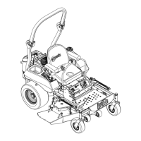
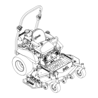
Figure 2
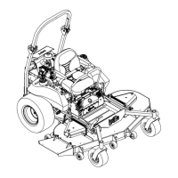
Figure 3
10. LOOSELY install lower roll bar hardware (four 3/8-
16 x 1 capscrews, four spring disk washers and
four 3/8-16 whizlock nuts) to the tubes on each
side. (Fig. 2).
Note: Be sure the spring disk washer cone is
installed towards the head of the capscrew.
11. For units with Kohler engines, secure oil drain
hose assembly to left-hand lower roll bar bracket
with 24” long plastic tie supplied (Fig 2). Clip off
excess tie.
12. Locate the latch pin assemblies (pin and hairpin
connected with a lanyard).
13. Insert a 1/2-13 x 3 1/4 capscrew (removed in step
5) into the bent tab washer on the lanyard of each
pin assembly (Fig. 3).
Note: Make sure the bent tab in the washer is
towards the head of the bolt.
14. Lightly oil the inside surfaces of the ear-shaped
plates at the upper end of the lower roll bar tubes
(Fig. 3).
15. Locate the upper u-shaped section of the roll
bar. Install the upper roll bar section using the
two 1/2-13 x 3 1/4 capscrews and two 1/2-13
hex flange lock nuts (removed in step 5). Do
not over tighten. Make sure upper roll bar can
pivot freely.
Notes:
• Make sure the capscrew and nuts are
installed with the nut to the inside of the roll
bar.
• Make sure the tab on the lanyard washer is
installed as shown and points toward the
front of the unit.
16. Raise the roll bar into the upright position and
secure with the latch pin assemblies on each
side. Install latch pin from outer surface of roll
bar assembly and secure with the hairpin to the
inside.
17. Torque all lower roll bar hardware attached to
the machine frame to 30 ft-lbs. (41-47 N-m).
18. Tighten the front knobs against the upper roll
bar ends.
Installing the Drive Wheels
1. Remove the 1/2-20 drive wheel nuts (installed
on studs of drive motors; See Fig. 2) and retain
for wheel mounting. Remove and discard
shipping brackets mounted on wheel hubs.
2. Mount drive wheels with the valve stem to the
outside of the unit. Secure using four (4) 1/2-20
wheel nuts removed in step 1.
3. Torque to 95 ft-lbs (128 NxM).
Checking Tire Pressure
1. Check the tire pressure in the drive tires. Proper
inflation for drive tires is 13 psi (90 kPa).
2. Adjust if necessary.
Servicing the Battery
The machine is shipped with a filled lead
acid battery.
1. Unhook seat latch and tilt seat up to gain access
to the battery.
Battery posts, terminals, and related
accessories contain lead compounds, chemicals
known to the State of California to cause cancer and
reproductive harm. Wash
hands after handling.
FOR KOHLER UNITS,
SECURE OIL DRAIN
HOSE IN THIS AREA

 Loading...