Safety
SafetyAlertSymbol
ThisSafetyAlertSymbol(Figure2)isusedbothin
thissetupinstructionsandonthemachinetoidentify
importantsafetymessageswhichmustbefollowedto
avoidaccidents.
Thissymbolmeans:ATTENTION!BECOME
ALERT!YOURSAFETYISINVOLVED!
Figure2
SafetyAlertSymbol
Thesafetyalertsymbolappearsaboveinformation
whichalertsyoutounsafeactionsorsituationsandwill
befollowedbythewordDANGER,WARNING,or
CAUTION.
DANGER:Whitelettering/Redbackground.Indicates
animminentlyhazardoussituationwhich,ifnotavoided,
Willresultindeathorseriousinjury.
WARNING:Blacklettering/Orangebackground.
Indicatesapotentiallyhazardoussituationwhich,ifnot
avoided,Couldresultindeathorseriousinjury.
CAUTION:Blacklettering/Yellowbackground.
Indicatesapotentiallyhazardoussituationwhich,ifnot
avoided,Mayresultinminorormoderateinjury.
Thismanualusestwootherwordstohighlight
information.Importantcallsattentiontospecial
mechanicalinformationandNoteemphasizesgeneral
informationworthyofspecialattention.
InstallingtheBaggerFrame
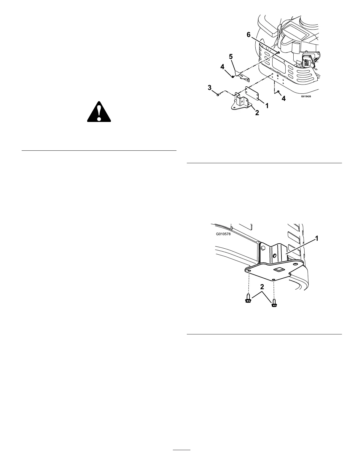
1.Usingtwo5/16-18x3/4inchcarriageboltandtwo
5/16-18inchangednylocnuts,installtheupper
supportbrackettorearofthemowerasshownin
Figure3.
Figure3
1.Spacer4.5/16inchangednylocnut
2.Lowersupportbracket5.Uppersupportbracket
3.5/16-18x1inchscrew6.5/16-18x3/4inchcarriage
bolt
2.Usingtwo5/16-18x1inchscrewsandtwo5/16
inchangednylocnuts,installthespacerandlower
supportbrackettotherearofthemower.
3.Securethelowersupportbrackettothebottom
ofthemowerframewithtwo5/16-18x3/4inch
self-tappingscrews(see
Figure4).
Figure4
1.Supportbracket2.5/16-18x3/4inchscrews
4.Insertthebaggerframeintothelowersupport
bracketandsecureitwithaclevispinandhairpinas
showninFigure5.
3