4. Electrical installation
4.1 General
The control can be used in two ways:
y Connected so the fan runs continuously independent of appliance operation (see paragraph 4.2).
y Interlocked with an appliance so the appliance operation indirectly controls the fan operation (see paragraph 4.3).
In both cases the control will still monitor and maintain a constant draft.
There are two types of safety systems available:
y Integrated Proven Draft Switch (standard)
y Integrated Proven Draft Switch with external Proven Draft Switch (accessory) backup
(see paragraph 4.4).
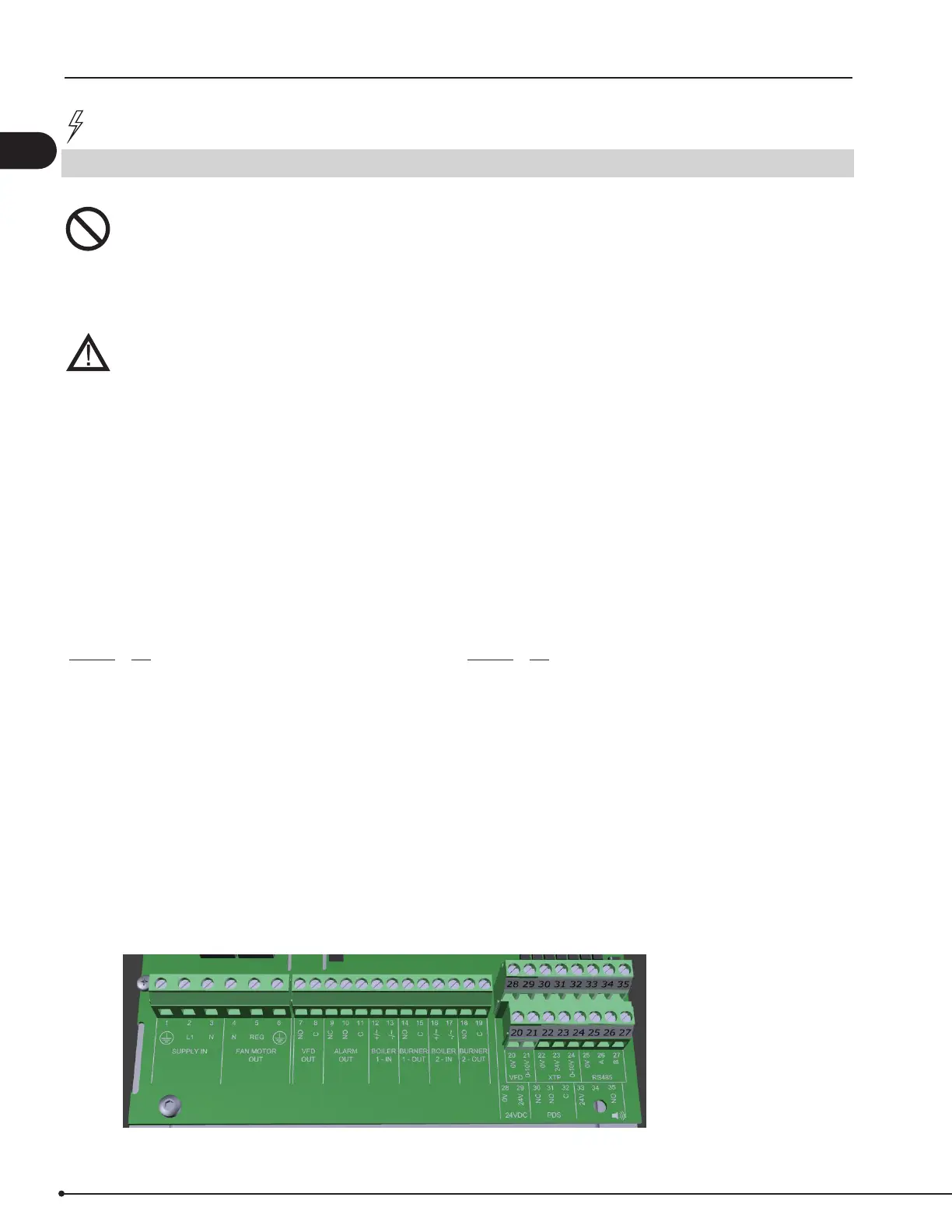
The terminals are connected as shown on g. 6:
Terminal Use
1 Power Supply-PE Ground
2 Power Supply-L1
3 Power Supply-N
4 Chimney Fan-N
5 Chimney Fan-L1 (Regulating)
6 Chimney Fan-PE Ground
7 VFD Relay NO
8 VFD Relay C
9 Alarm Out-NC
10 Alarm Out-NO
11 Alarm Out-C
12 Voltage Input from Appliance / Boiler 1 thermostat
Optocoupler (+) (10-230 VAC/DC)
13 Voltage Input from Appliance/Boiler 1 thermostat
Optocoupler (-) (10-230 VAC/DC)
14 Burner 1 relay contact-Normally Open (max. 230 VAC, 4 Amps.)
15 Burner 1 relay contact-Common (max. 230 VAC, 4 Amps.)
16 Voltage Input from Appliance / Boiler 2 thermostat
Optocoupler (+) (10-230 VAC/DC)
17 Voltage Input from Appliance / Boiler2 thermostat
Optocoupler (-) (10-230 VAC/DC)
Terminal Use
18 Burner 2 relay contact-Normally Open (max. 230 VAC, 4 Amps.)
19 Burner 2 relay contact-Common (max. 230 VAC, 4 Amps.)
20 Control signal VFD 0 VDC
21 Control signal VFD 0-10 VDC
22 XTP-0 VDC Power Supply (transducer)
23 XTP-24 VDC Power Supply (transducer)
24 XTP-0-10 VDC Return Signal (transducer)
25 RS485 0V
26 RS485 A
27 RS485 B
28 0VDC Power Supply
29 24 VDC Power Supply (Max 100 mA)
30 PDS-NC (Normally Closed) Proven Draft Switch
31 PDS-NO (Normally Open) Proven Draft Switch
32 PDS-C (Common) Proven Draft Switch
33 Buzzer-24 VDC Supply
34 Not used
35 Buzzer Signal
DANGER
Turn o electrical power before servicing. Contact with live electric components can cause shock or
death.
Mettre hors tension avant toute opération de maintenance. Le contact avec des composants sous
tension peut entraîner un choc électrique ou la mort.
NOTE
EBC24 is designed for 1x120 VAC power supply only. Fan output is regulating on the phase side and
cannot be connected to other circuits.
EBC24 est conçu uniquement pour une alimentation de 1x120 VCA. La sortie du ventilateur est réglée
sur le côté phase et ne peut pas être connectée à d’autres circuits.
Fig. 6
8
3120066 MEC24 US 20210325