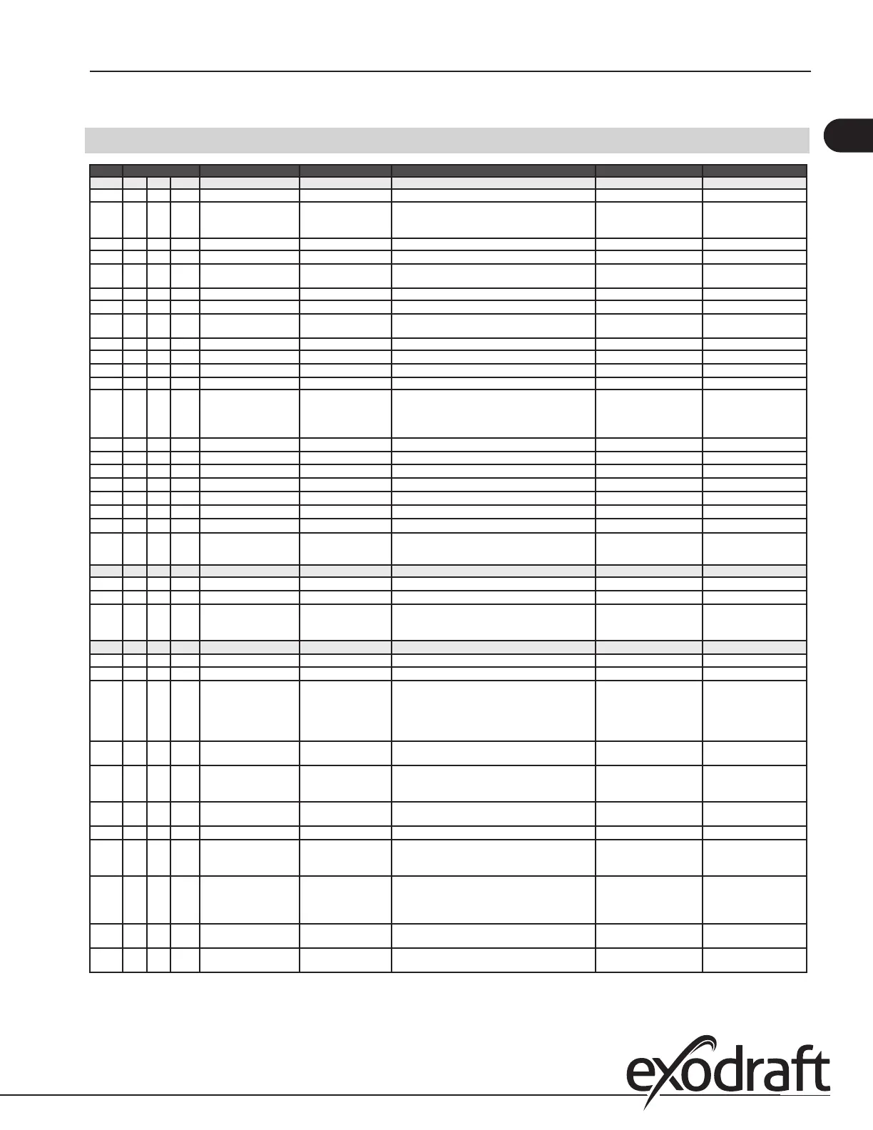
6.2 Settings
Menu Sub-menu function Display Description Range Default
1 Exhaust EXHAUST
11 Draft set point SET EXHAUST Adjustment of exhaust setpoint. 2%-95% af sensor 17%
12 Operation mode EXHAUST MODE Continuous or intermittent operation. In inter-
mittent mode the exhaust fan runs only if one
or more boiler inputs are active.
Continuous/
Intermittent
Intermittent
13 Pre-purge PRE-PURGE Pre-purge settings.
131 Time TIME Pre-purge time in seconds 0-1800 0
132 Operation mode SPEED MODE Select variable if the pre-purge should be con-
trolled by the XTP-sensor or have a xed speed.
Variable / FIX 20-100% FIX 100%
14 Post-purge POST-PURGE
141 Time TIME Post-purge settings. 0-1800 0
142 Operation mode SPEED MODE Select variable if the post-purge should be con-
trolled by the XTP-sensor or have a xed speed.
Variable / FIX 20-100% Variable
15 Sensor SENSOR
151 Min. pressure RANGE MIN XTP minimum pressure in Pa. -500 – 500 Pa 0
152 Max. pressure RANGE MAX XTP Maximum pressure in Pa. 0 – 1000 Pa 150 Pa
16 Parameters PROPERTIES
161 Alarm limit draft ALARM LIMIT Select the alarm limit of the draft. The value is in
% of the set point.
If 167 = "Negative" ->50
- 80 %.
If 167 = "Positive" -> 150
- 300 %"
64 % (167 = "Negative")
144 % (167 = "Positive")
162 Alarmdelay ALARM DELAY Select a alarm delay from 0-120 seconds. 0 – 120 s 15
163 Min. voltage SPEED MIN Mimimum speed of the fan 0 – MENU 164 15 %
164 Max. voltage SPEED MAX Maksimum speed of the fan. MENU 163-100% 100
165 Xp EXHAUST Xp Proportional gain. 0-30 15
166 Ti EXHAUST Ti Integral gain. 0-30 8
167 Sampling rate SAMPLING RATE Set the sampling rate for the PID Loop 1-10 10
168 Pressure type PRESSURE MODE Positive or negative pressure in the stack. Positive or Negative Negative
169 Application APPLICATION Sets if the control has to work as Exhaust
or Intake
Exhaust / Intake Exhaust
2 ALARM
21
Alarm Status
ERROR
The error is shown here
22
Alarm log
ERROR LOG The last 10 alarms will be saved in the menu.
23
Reset
RESET Selecting "AUTO" will automatic reset the
alarm after 15 seconds. If "MAN" is selected,
the "X" has to be pressed.
MAN / AUTO AUTO
3 Service
SERVICE
31
Version no.
VERSION Software version is showed.
32
I/O
I/O-VIEW
321 BURNER I/O AUX OUT XXX
AUX IN XX
In this menu the status of the boiler I/O is
shown. By pressing athe AUX OUT relays
can be activated by pressing up and down.
Multiple activations of the a button will move
from relay 1 to 6
322 EXHAUST I/O EXH XTP x.xV OFF
EXH VFD x.xV OFF
XTP, VFD and VFD relay status for Exhaust.
323 Draft input DRAFT INPUT ON/
OFF
Draft Input I/O status.
324 Alarm relay ALARM OUTPUT
ON/OFF
Alarm relay output status.
33 Options OPTION
331 Bearing cycle BEARING CYCLE Selecting "YES" will enable a bearing cycle on
present fans, if the boilers has not been active
for 24 hours.
ON/OFF ON
332 Allow prime Selecting a number from 0-250 will enable the
prime function. This allows the boilers to be
activated even though no sucient draft is
present.
0-250 s / o O
333 Draft Input Delay DRAFT INPUT DELAY The delay before the control goes into Fraft
Alarm
0-20 s 0 s
34 Factory reset FACTORY If "YES" is selected, a factory reset will be
performed.
YES/NO NO
17
3120066 MEC24 US 20210325