480403 V1.0 6/07 5
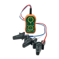
Check Motor Turn Direction (contact method)
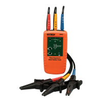
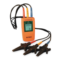
1. Connect the supplied color-coded test leads to the meter’s test
lead input jacks at the top of the meter.
2. Connect the test (alligator) probes to the three motor connections
(L1 to U, L2 to V, and L3 to W).
3. Press the ON/OFF button. The green ON indicator shows that the
instrument is ready for testing.
4. Turn the motor shaft half of a revolution towards the right.
5. The clockwise and counter-clockwise arrows with the left/right ‘L’
or ‘R’ icons display the orientation of the motor.
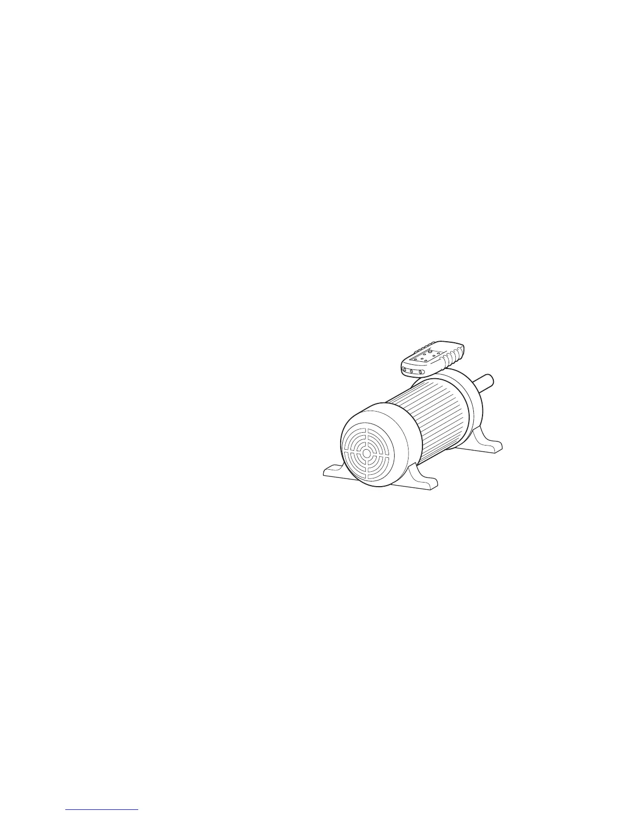
Check Motor Turn Direction (non-contact method)
1. Disconnect the test leads from the meter and from any other
devices under test.
2. Hold the meter close (one
inch or closer) to the motor,
parallel to the length of the
motor shaft.
3. The bottom of the meter
should face the drive shaft
and the back of the meter
should be flush with the motor
(refer to diagram at right).
Note: There is an orientation
symbol on the meter to assist.
4. Press the ON/OFF button. The green ON indicator shows that the
instrument is ready for testing.
5. The orientation of the motor is represented by the clockwise and
counter-clockwise arrows with the left/right ‘L’ or ‘R’ icons display.
Face the rear of the motor (meter will appear upside down) when
reading the status of the display LEDs.
Note: The meter will not operate with motors controlled by
frequency converters.