Do you have a question about the Extech Instruments VT30 and is the answer not in the manual?
Symbols indicating potential hazards or required actions for safe use.
Important warnings and guidelines for safe operation of the meter.
Specific rules and limitations for using the meter safely.
Step-by-step guide for measuring AC/DC voltage with the tester.
Procedure for detecting AC voltage using a single test probe.
How to perform low impedance voltage measurements to detect phantom voltages.
Testing for continuity and its resistance limits.
Steps for safely replacing the tester's batteries.
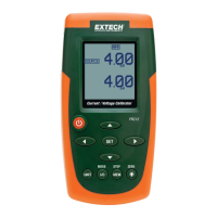
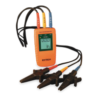
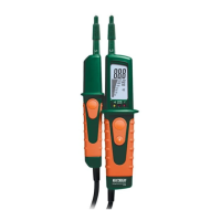
The Extech VT30 is an LCD Multifunction Voltage Tester designed for safe and reliable electrical measurements. This device measures AC voltage up to 480V and DC voltage up to 690V, providing both an LCD digital readout and a stepped voltage bargraph indicator for clear visual feedback. It also features LEDs to indicate positive and negative polarity, enhancing user safety and understanding of the circuit conditions.
One of the key usage features of the VT30 is its automatic operation. The voltage tester turns on automatically when voltages higher than 4.5V AC/DC are detected, simplifying the measurement process. To perform a voltage measurement, users simply touch the positive (L2) and negative (L1) test leads to the device or circuit under test. If the voltage exceeds 4.5V AC/DC, the LCD will illuminate and display the reading, complemented by the stepped voltage bargraph. For AC voltages, a dedicated LED will light, and an "AC" icon will appear on the display. For DC voltages, a "DC" icon will be displayed, and a minus sign will precede the digital readout if the voltage is negative.
The VT30 also includes a single-lead AC voltage detection feature, allowing users to check for the presence of voltage between 100V and 480V using only the positive test lead (L2). In this mode, an LED will light if voltage is present, though the actual voltage value is not displayed. This provides a quick and convenient way to identify live circuits.
A significant feature for troubleshooting is the low impedance voltage measurement. This mode suppresses capacitive voltage, ensuring that the reading reflects the actual voltage applied, which is particularly useful for identifying "phantom voltages." To use this, users hold both test tips on the measuring points and simultaneously press the two low impedance test buttons. A dedicated LED will light, and the applied voltage will be displayed on the LCD. It's important to note the duty cycle limitations for this mode: 5 seconds for voltages up to 250V and 3 seconds for voltages up to 690V, with a 10-minute cool-down period between readings. Users should also be aware that measuring from hot to ground in this mode may trip GFCI-equipped circuits.
For continuity testing, the VT30 can measure resistance and alert the user if the value is less than 200kΩ. Before performing a continuity test, it is crucial to ensure that power to the device or circuit under test is off and all capacitors are discharged. Once these precautions are taken, users touch the test tips to the device. If the resistance is below 200kΩ, the tester will emit an audible alert, display "000" on the LCD, and illuminate the continuity LED.
The device also incorporates a built-in flashlight, activated by pressing and holding a dedicated button. Releasing the button turns the flashlight off, with the light automatically extinguishing after approximately 12 seconds. This feature is invaluable for illuminating test connections in dimly lit environments.
Maintenance of the Extech VT30 is straightforward. The device indicates low battery voltage with a "BAT" icon in the lower right of the display, prompting users to replace the two 'AAA' alkaline batteries. To replace the batteries, the meter must first be disconnected from any test device or circuit. Users then loosen the recessed Phillips head screw at the bottom of the tester (without removing it) and pull the lower portion of the meter off to expose the batteries. After replacing the batteries, observing proper polarity, the meter is slid back together, and the screw is re-secured.
For cleaning and storage, it is essential to ensure the test leads are not connected to any circuit or device. The meter should be wiped with a damp cloth as needed, avoiding abrasives, solvents, or other harsh cleaners. For long-term storage, the batteries should be removed, and the device should be kept away from extreme temperatures and humidity to ensure its longevity and reliable service. The VT30 is designed with double insulation and is rated for Category IV 600V and Category III 1000V, Pollution Degree 2, emphasizing its robust safety features.
| Type | Vibration Meter |
|---|---|
| Display | LCD |
| Power Supply | 9V battery |
| Displacement | 0.001 to 1.999 mm |
| Frequency | 10Hz to 1kHz |
| Resolution | 0.01 mm/s |
| Accuracy | ±(5% + 2 digits) |
| Acceleration | 0.1 to 199.9 m/s² |
| Velocity | 0.1 to 199.9 mm/s |