EX330-EU-ENG – V4.2 1/08
10
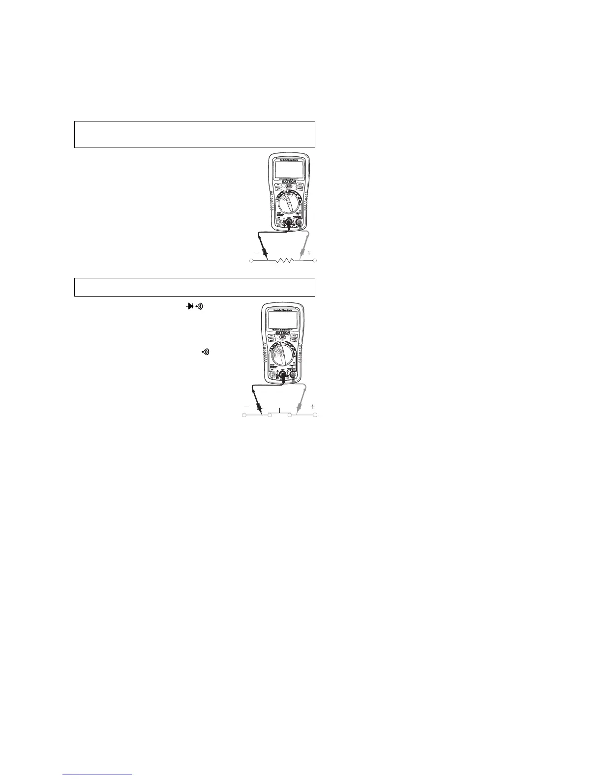
RESISTANCE MEASUREMENTS
WARNING: To avoid electric shock, disconnect power to the unit under
test and discharge all capacitors before taking any resistance
measurements. Remove the batteries and unplug the line cords.
1. Set the function switch to the Ω position.
2. Insert the black test lead banana plug into the
negative COM jack.
Insert the red test lead banana plug into the
positive Ω jack.
3. Touch the test probe tips across the circuit or
component under test. It is best to disconnect
one side of the circuit under test so the rest of
the circuit will not interfere with the resistance
reading.
4. Read the resistance in the display.
CONTINUITY CHECK
WARNING: To avoid electric shock, never measure continuity on circuits or
wires that have voltage on them.
1. Set the function switch to the position.
2. Insert the black lead banana plug into the
negative COM jack.
3. Insert the red test lead banana plug into the
positive Ω jack.
4. Use the MODE button to view the icon on
the display.
5. Touch the test probe tips to the circuit or
wire you wish to check.
6. If the resistance is less than approximately
100Ω, the audible signal will sound. If the
circuit is ‘open’ (bad), the display will
indicate “OL”.