The rear panel of the switch includes:
• 3 xed fan modules
• Grounding lug
• 1 AC power inlet connector
• 1 power supply slot
Figure 16: 5420F-48P-4XL Rear Panel
1 = Grounding lug
3 = AC power inlet connector
2 = Fixed fan modules 4 = Power supply slot
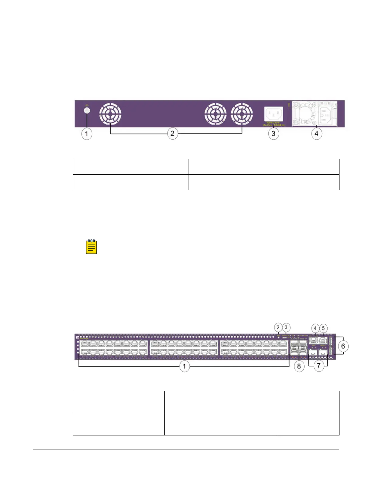
5420F-48T-4XE Switch Features
The front panel of the 5420F-48T-4XE switch includes:
• 48 10/100/1000BASE-T full/half duplex (autosensing) MACsec capable ports
Note
Half-duplex is not supported on these ports when operating at 1Gbps.
• 4 1/10Gb SFP+ MACsec capable uplink ports (unpopulated)
• 2 Stacking/SFP-DD ports (unpopulated)
• 1 Serial console port (RJ-45)
• 1 10/100/1000BASE-T out-of-band management port
• 2 USB Type-A ports for management or external ash
• 1 USB Micro-B console port
Figure 17: 5420F-48T-4XE Front Panel
1 = 10/100/1000BASE-T ports
4 = 10/100/1000BASE-T out-of-band
management port
7 = SFP-DD
stacking ports
2 = Mode button 5 = RJ-45 serial console port 8 = 1/10G SFP+
ports
ExtremeSwitching 5420 Series Overview 5420F-48T-4XE Switch Features
ExtremeSwitching 5420 Series Hardware Installation Guide 25
 Loading...


