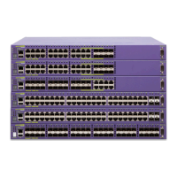
External Power Supply (45019)
Consolidated "e" Series Hardware Installation Guide 77
1 Place the EPS-LD unit upright on a hard flat surface, with the side you want to face to the front of
the switch toward you.
2 Remove the mounting bracket kit (including screws) from the packaging.
3 Locate a mounting bracket over the mounting holes on one side of the unit.
4 Insert the screws, as shown in Figure 21, and fully tighten the screws with a #1 Phillips screwdriver.
Figure 21: Fitting the mounting bracket
5 Repeat steps 2 through 4 for the other side of the EPS-LD unit.
6 Insert the EPS-LD unit into a 19-inch rack.
NOTE
Mount the EPS-LD so that the output connectors are on the same side as the external connector on
the connecting switch. If you mount the EPS-LD with the connectors facing in the opposite direction
as the Extreme switch connector, leave at least 1 U between the switch and the EPS-LD through
which to slide the cables. Do not route the cables around the equipment rack.
7 Insert the screws into the rack and the mounting bracket on both sides of the unit and fully tighten
with a suitable screwdriver.
Connecting the EPS-LD unit
CAUTION
Do not attach the AC power cord to the EPS-LD unit until the unit is properly grounded at the electrical
outlet and the redundant power supply cable is connected.
1 Connect the keyed end of the EPS-LD cable to the power supply unit(s). The key is a plastic tab on
the cable connector housing that fits into the EPS-LD unit to ensure correct alignment of the
connector.
See Figure 22 for details on the connector key, and see Figure 23 to locate the connectors on the
EPS-LD unit and on the switch.
NOTE
The cable length is 1 meter.
2 Connect the other end of the power supply cable to the Extreme switch.
The connector fits the slot in only one direction.
Collin's
ES4K026
XM_05

 Loading...