2
SMP300 Series • Setup Guide (Continued)
3
B-Y
R-Y VID
/Y
5
4
HDMI
3G/HD/SDI
INPUTS-CH B
AUDIOL R
I
H J K
1
HDMI
AUDIO
L R
L R
LOOP THRU
2
INPUTS-CH A
L M
F G
Control System and External Device Connections
The SMP 300 Series models can be congured and controlled from the remote port (see figure 1,
E
on previous
page) or the front panel mini USB B Cong port (see figure 4,
B
on page 3) using SIS commands and
DataViewer via telnet port 23, or from the LAN port using a standard web browser. Because the LAN port must be
connected for recording upload and streaming output, Extron recommends using it for conguration, remote control,
and rmware upgrades.
B
USB storage device — Attach an external USB storage device to save recorded les. The storage device can
be any standard external hard drive or USB ash drive formatted with a compatible le system.
NOTE: SMP 300 Series devices can detect and record to USB storage devices using FAT32, VFAT long file
name extensions, EXT2, EXT3, EXT4 file systems, or NTFS-formatted storage volumes.
C
USB keyboard and mouse — Two (2) USB type A ports for attachment of a keyboard and mouse.
When a keyboard and mouse are connected, the user can toggle (CTL+ALT+S) the HDMI output (see
figure 1,
N
) between the standard preview output and the internal browser view.
D
Digital I/O — This 3.5 mm, 5-pole captive screw connector provides four user-dened digital inputs and
outputs.
E
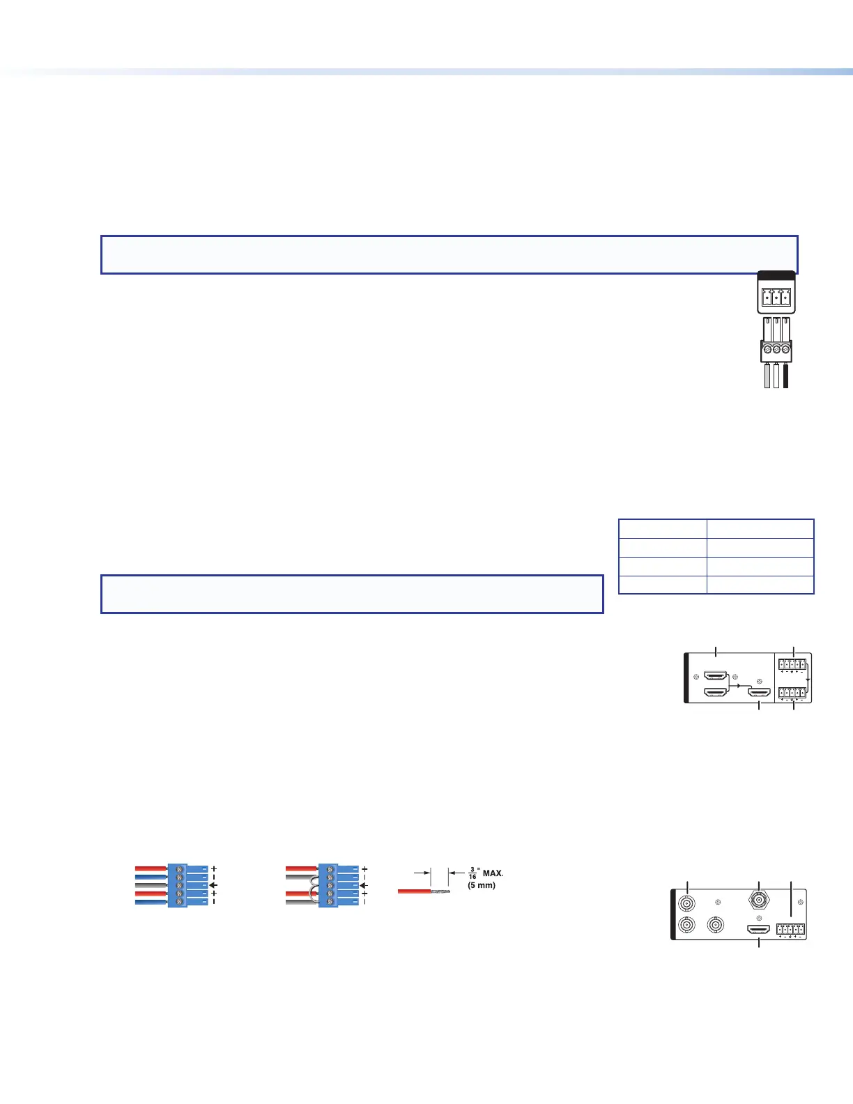
Remote — To control the SMPmodels using SIS commands over RS-232, connect the host
RS-232 cable to the rear panel (see the illustration at right) with a 3-pole captive screw connector for
bi-directional (±5V) serial host control. The default protocol for this port is 9600 baud, no parity, 8 data
bits, 1 stop bit, and no flow control (handshaking).
P
Reset button and LED — The SMPmodels have several reset modes to return user-dened conguration
settings or all settings back to factory defaults. The LED blinks to indicate the desired reset mode, and provides
the reset status during the reset operation. For information on selecting the reset mode, see the SMP300 Series
User Guide.
Q
RJ-45 Ethernet connector (LAN) — Use a standard Ethernet cable to
connect to a network. The table at right has the default network settings.
NOTE: To connect the SMPmodels directly to a computer Ethernet port, use
crossover Ethernet cables.
Input Connections
The audio and video inputs are grouped into channel A (
G
) and channel B (
K
). Channel
A analog input can be selected for video inputs 1 or 2, and channel B analog audio can be
selected for video inputs 3, 4, or 5.
F
HDMI input (1 and 2) — Connect an HDMI (or DVI with a suitable adapter) source device to
input 1, input 2, or both.
G
Channel A analog audio input — Connect a balanced or unbalanced stereo line level audio device to this
5-pole 3.5 mm captive screw connector. Channel A analog audio can be selected for output with HDMI inputs
1 and 2 instead of the embedded audio. Wire the connector as shown in gure 2 (see Attention on next page
before wiring).
When input 1 or 2 is selected, audio is selected from either the HDMI embedded audio, ChA analog audio, or
the audio can be set to Off (see Audio Input Selection on page 6).
Unbalanced Stereo InputBalanced Stereo Input
(high impedance)(high impedance)
Do not tin the wires!
Tip
Slee
ve(s)
Ring
Ring
Tip
Left
Right
Sleeve
Sleeve
Tip
Left
Right
Figure 2. Audio Input Captive Screw Connector Wiring
H
Analog video input 3 — Attach component video (B-Y, R-Y, Y) to the three BNC
connectors, or composite video to the VID/Y BNC connector.
I
HDMI input 4 — Connect an HDMI (or DVI with a suitable adapter) source device to the input 4 connector.
J
Serial digital video input 5 (optional) — Attach a 3G/HD/SDI video source to this BNC connector.
IP Address: 192.168.254.254
Subnet Mask: 255.255.0.0
Default Gateway: 0.0.0.0
DHCP: OFF
e
Tr
Tx Rx
RS-232
G