3
K
Channel B analog audio input — Connect a balanced or unbalanced stereo line level audio device to this
5-pole 3.5 mm captive screw connector. Channel B audio can be selected from either the HDMI embedded
audio, or the ChannelB analog audio, or the audio can be set to OFF (see Audio Input Selection on page 6).
Output Connections
L
HDMI loop-thru output — Connect an HDMI (or DVI with suitable adapter) display device to the HDMI LOOP
THRU to view the selected input 1 or input 2 (see figure 1 on page 1).
M
Audio loop output — Connect a balanced or unbalanced stereo line level audio device to this 5-pole 3.5 mm
captive screw connector. Audio is always from the Channel A audio input
G
.
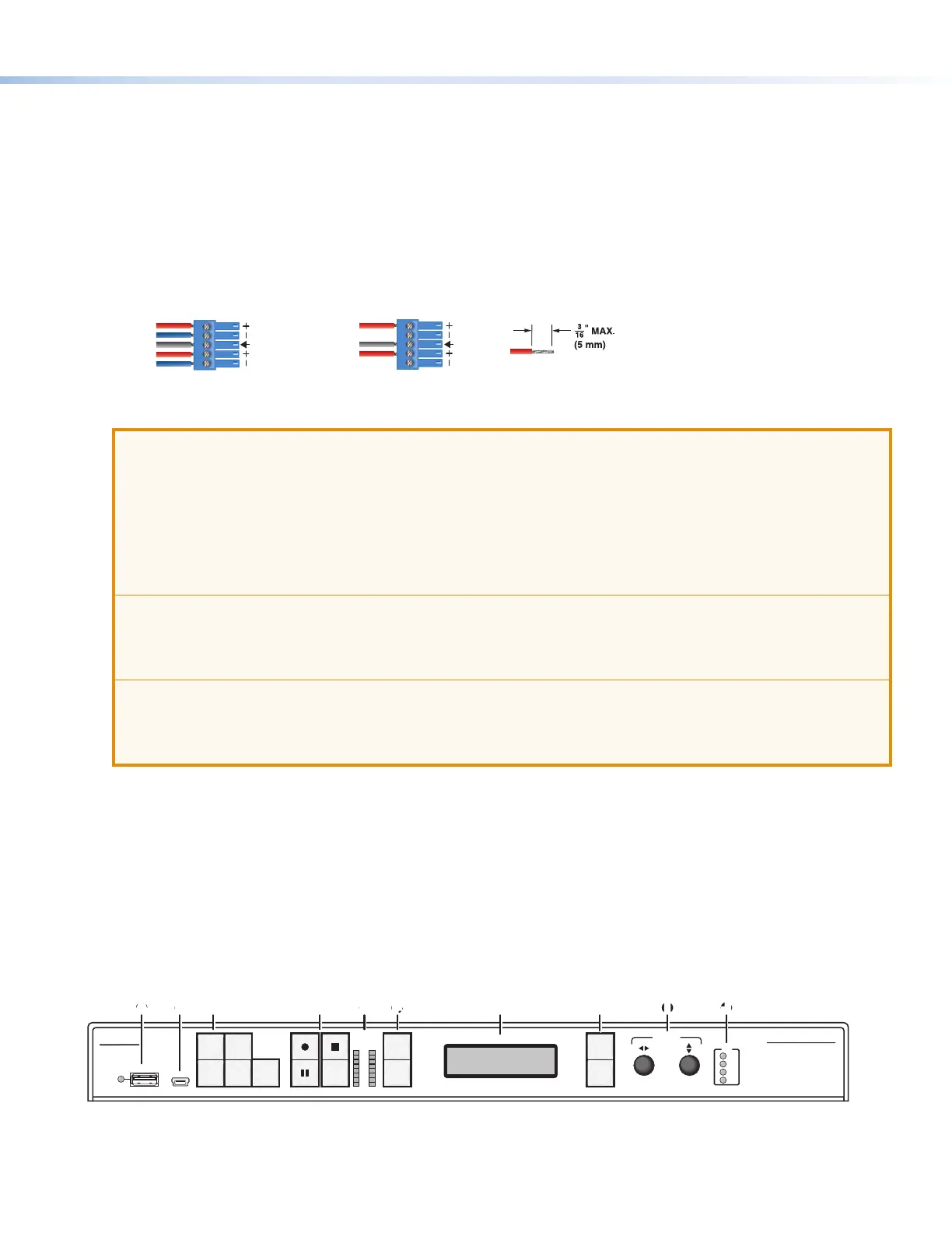
Wire the connector as shown in gure 3.
Balanced Audio Output Unbalanced Audio Output
Left
Tip
Sleeve(s)
NO Ground Here
NO Ground Here
Tip
Right
Tip
Sleeve(s)
Ring
Ring
Tip
Left
Right
Figure 3. Audio Output Captive Screw Connector Wiring
ATTENTION:
• The length of the exposed wires in the stripping process is critical. The ideal length is 3/16 inch (5 mm).
If longer, the exposed wires may touch, causing a short circuit between them. If shorter, the wires can
be easily pulled out even if tightly fastened by the captive screws.
• La longueur des câbles exposés est primordiale lorsque l’on entreprend de les dénuder. La longueur
idéale est de 5mm (3/16inches). S’ils sont un peu plus longs, les câbles exposés pourraient se
toucher et provoquer un court circuit. S’ils sont un peu plus courts, ils pourraient sortir, même s’ils sont
attachés par les vis captives.
• Do not tin the wires. Tinned wires are not as secure in the captive screw terminals <connector> and
could pull out.
• Ne pas étamer les câbles. Les câbles étamés ne sont pas aussi bien xés dans les terminaisons des
<connecteurs> à vis captives et pourraient sortir.
• For unbalanced audio connect the sleeves to the ground contact. DO NOT connect the sleeves to the
negative (–) contacts.
• Pour l’audio asymétrique connectez les manchons au contact au sol. Ne PAS connecter les manchons
aux contacts négatifs (–).
N
HDMI preview output — Connect an HDMI (or DVI with a suitable adapter) display device to this HDMI output
connector. The preview output switches between the record preview content and the internal browser using an
attached USB keyboard and mouse.
O
Analog audio output — Connect a balanced or unbalanced stereo line level audio device to this 5-pole 3.5 mm
captive screw connector (see figure 1). Wire the connector as shown in figure 3.
The audio output is selected from Channel A, from Channel B, or a mix of both Channel A and Channel B (see
Audio Output Selection on page 7). Default is Ch A + Ch B.
Front Panel Features
USB STORAGE
SMP 300 SERIES
PRESENTATION CAPTURE RECORDER
Extron
CONFIG
ADJUST
AUDIO
CHANNEL A
CHANNEL B
L R
1
2
3
4
5
LAYOUT
PRESET
SWAPSWAP NEXT
MENU
NEXTMARK
I/O
1
2
3
4
BB CC DD EE FF GG HH II JJAA
Figure 4. SMP300 Series Model Front Panel