13
ENGLISHENGLISH
412 COMPACT AUTOMATION SYSTEM
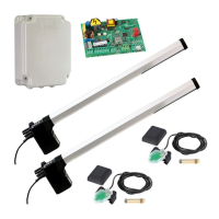
The FAAC 412 COMPACT AUTOMATION SYSTEM for swing gates
comprises two electromechanical operators which drive the
gate leaves by means of a worm screw.
The system locks mechanically; therefore no electric lock is
required.
The 410 MPS control unit supplied with the automation kit
enables programming and control of system operation.
1. DESCRIPTION AND TECHNICAL SPECIFICATIONS
a
Motor Unit
b
Power cable
c
Worm screw
d
Front bracket
e
Rear bracket
f
Cable cover
g
Cover
Fig. 1
162
5
7
3
4
Fig. 2
a
Power supply+Earth terminal
block
b
Flashing light and motor terminal
block
c
Low voltage terminal block
d
Decoder card connector
e
Torque adjusting trimmer
f
Pause time adjusting trimmer
g
Opening/Closing time
adjusting trimmer
h
Closing leaf delay time
adjusting trimmer
i
Programming microswitches
j
Fuse F1 (motor) 5x20 5 A /250
V rapid
k
Fuse F2 (accessories) 5x20 800
mA /250 V delayed
l
Fuse F4 (transformer) 5x20 250
mA /250 V delayed
12
11
4
8
7
6
5
3
9
2
1
10
Table 1:
412 operator technical specifications
Power supply 230 V~ ( +6% -10%) - 50 Hz
Absorbed power 350 W
Current drawn 1.5 A
Electric motor 4 poles - 1400 rpm
Motor winding thermal cutout 140 °C
Capacitor 8 µF / 400V
Max. thrust/traction force 320 daN
Rod stroke 290 mm
Rod speed 1.6 cm/s
Temperature range -20 °C +55 °C
Operator weight 6.5 Kg
Housing protection IP 53
Duty cycle 18 cycles/hour
Maximum leaf length 1.80 m
Table 2
:
410 MPS control unit technical specifications
Power supply 230 V~ ( +6% -10%) - 50 Hz
Absorbed power 10 W
Max. motor load 800 W
Max. accessories load 0,25 A
Temperature range -20 °C +55 °C
Fuses 3 (see fig. 2)
Operation logics Automatic/Semi-automatic/Safety/
Step-by-step semi-automatic
Opening/closing time Adjustable by trimmer (from 0-62 seconds)
Pause time Adjustable by trimmer (from 0-240 seconds)
Closing leaf delay time Adjustable by trimmer (from 0-28 seconds)
Opening leaf delay time 2.5 seconds (fixed)
Thrust force Adjustable by trimmer
Terminal block inputs Open/Stop/Opening safeties/
Closing safeties/mains power + earth
Terminal block outputs Flashing light - motors - 24 Vdc
accessories power supply
Quick connector Decoding cards - RP 433 SL/DS
Microswitch programmable Operating logics -
functions Closing safeties logics
Housing dimensions 265 x 204 x 85
Housing protection IP 55
Fig. 3
2. STANDARD INSTALLATION LAYOUT
a
Operators (require 2 junction boxes)
b
Photocells
c
410 MPS control unit
d
T10 pushbutton
e
Receiver
f
Flashing light
Notes:
1)
Use suitable rigid/flexible pipes for laying power cables.
2)
Always keep low voltage accessory cables separate
from 230V~ power cables. To avoid interference, use
separate sheaths.

 Loading...