12
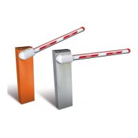
4.4. INSTALLING AND ADJUSTING THE BALANCING SPRING
1) Check if the balancing spring matches the type of
beam installed: see chapter 8.
2) Take the bronze bush (fig.7 ref.1) from the supplied
package, fit it in the tie-rod (fig.7 ref.2) and secure it to
the equaliser with M10 screw and washer (fig.7 ref.4).
3) While always keeping the beam in vertical position,
assemble the tie-rod (fig.7 ref.2) on the spring (fig.7
rif.3), supplied separately.
4) Release the operator (see chapter 6) and position the
beam at 45°, then adjust the tie-rod and set the spring
until the weight of the beam is balanced in that position.
5) Restore normal operation as described in chapter 7.
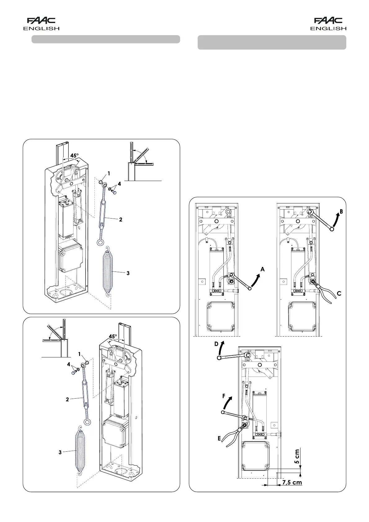
4.5 CONVERTING FROM RIGHT-HAND TO LEFT-HAND
VERSION
Procedure for converting a right-hand version to left-hand:
Release the operator.
Loosen the connection (fig.8 ref.A)
Provisionally remove the screw securing the piston (fig. 8
ref.B) and the seeger ring (fig.8 ref.C).
Turn the rocker arm.
Position the piston on the left and secure it with the screw
(fig.8 ref.D) and seeger ring (fig.8 ref.E) you had previously
removed.
Tighten the connection (fig.8 ref.F).
Re-lock the operator.
Remove the enclosure of the electronic equipment and re-
install it on the left side of the bonnet, using the existing holes
(The design makes it possible to secure the enclosure
shifted by 7.5 cm to the left, and 5 cm higher than the
original position).
Change over the connectors of the stroke-limit sensors (J6
and J9 on the 596/615BPR equipment).
fig.7/A
fig.7/B
fig.8