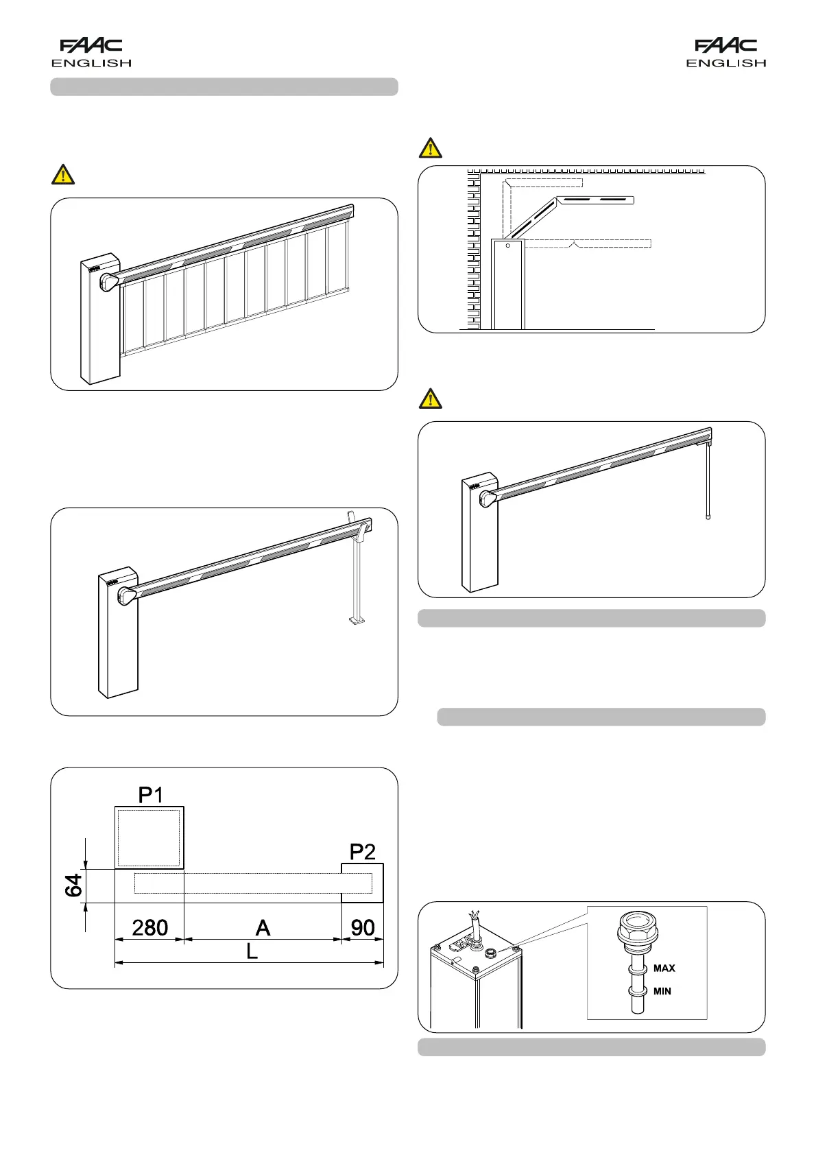
14
fig. 15
Dimensions are in mm.
POSITIONING THE FORK SUPPORT FOUNDATION PLATE
To position the fork support foundation plate, refer to fig.15
where:
P1 = barrier foundation plate
P2 = fork support foundation plate
L = beam length (in mm)
A = L-385 (in mm)
fig. 18
fig. 13
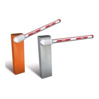
FORK SUPPORT (fig.14)
The fork has two functions:
- it prevents the beam, when closed, from bending and
splitting if its end is stressed by extraneous forces.
- it allows the beam to rest when closed and thus prevents
the profile bending downward.
fig. 14
ARTICULATION KIT (fig.16)
The articulation kit makes it possible to articulate a rigid
beam to a maximum ceiling height of 3 m (see specific
instructions).
If an articulation kit is installed, the balancing
spring must be adapted.
9. AVAILABLE ACCESSORIES
SKIRT KIT (fig.13)
The skirt kit increases visibility of the beam.
It is available in lengths from 2 m to 3 m.
If a skirt kit is installed, the balancing spring must
be adapted.
fig. 16
END FOOT (fig.17)
The end foot allows the beam to rest when closed and thus
prevents the profile bending downward.
If a foot is installed, the balancing spring must be
readjusted.
fig. 17
10.MAINTENANCE
Whenever doing maintenance, always check correct
settings of the by-pass screws, system balancing, and
efficiency of safety devices.
10.1. TOPPING UP OIL
Periodically check quantity of oil inside the tank.
An annual check is sufficient for low to medium use
frequency; for heavier duty, check every 6 months.
The level must not fall below the low mark on the stick
(fig.18).
To top-up, unscrew the filling plug (fig.18) and pour oil to
MAX level on the stick.
Use only FAAC HP OIL oil and no other.
11.REPAIRS
For repairs, contact FAAC’s authorised Repair Centres.