13
B
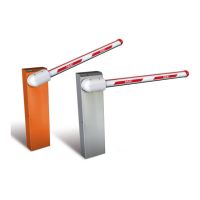
fig.9
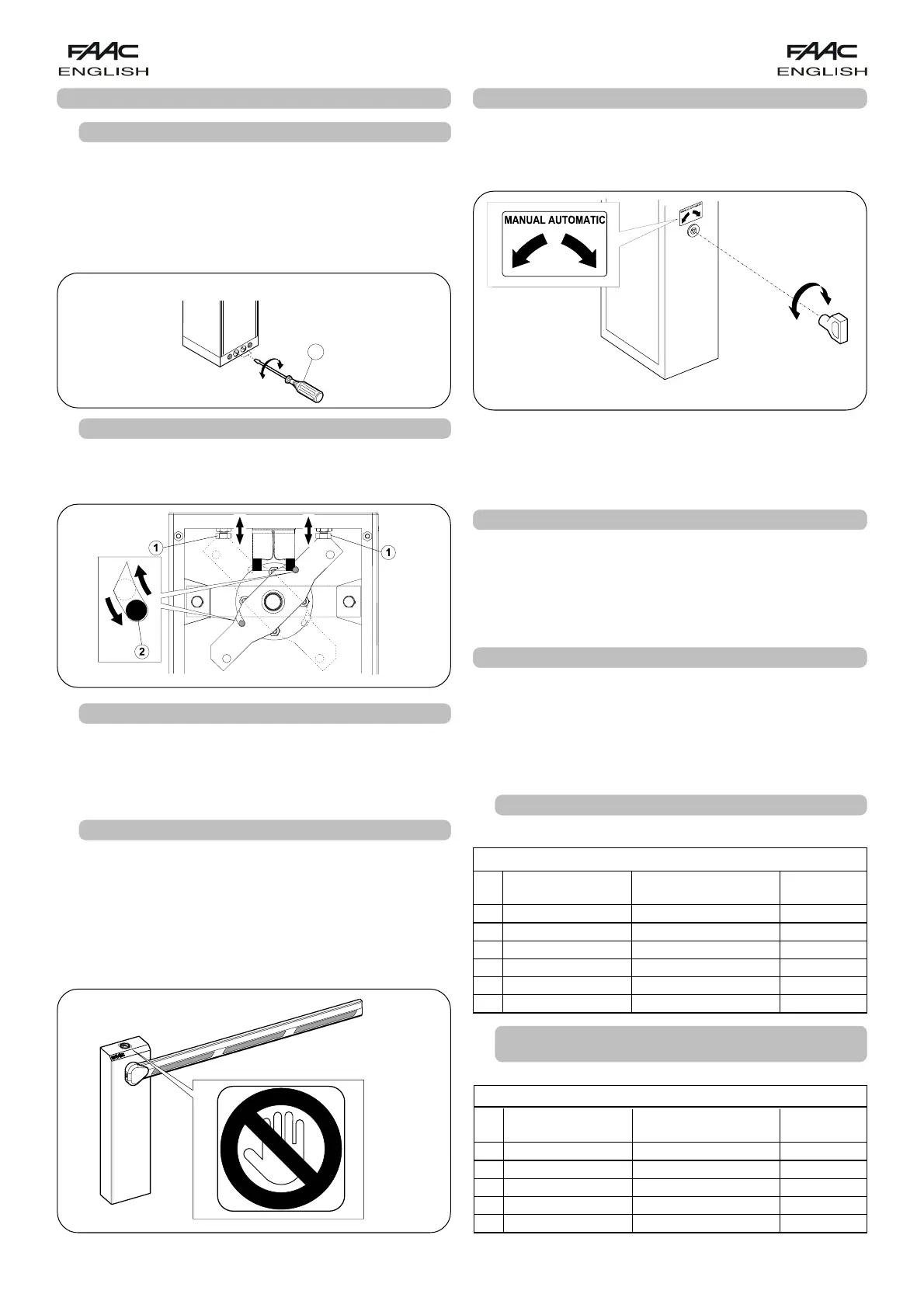
- Fit the standard triangular key (Fig.12) in the lock and turn
it anti-clockwise through 1 turn.
- Open and close the barrier manually.
7. RESTORING NORMAL OPERATION MODE
To prevent an involuntary pulse from activating the barrier
during the manoeuvre, before restoring normal operation,
switch off power to the system, and turn the triangular key
clockwise until it stops, and then remove it.
8. BALANCING SPRINGS
The 615BPR automatic system requires a balancing spring,
which must be ordered separately. The spring varies
according to length and type of beam (rigid, skirt or
articulated).
Consult the tables below to see if the spring matches.
8.1. SPRINGS FOR RIGID AND SKIRTED BEAMS
fig. 12
6. MANUAL OPERATION
If the barrier has to be moved manually due to a power cut
or fault of the automatic system, use the release device as
follows:
fig. 11
5.4 AUTOMATION TEST
After installation, apply the danger warning sticker on the
top of the upright (Fig 11).
Check operating efficiency of the automatic system and
all accessories connected to it.
Hand the “User’s Manual” to the Client, explain correct
operation and use of the barrier, and indicate the potentially
dangerous areas of the automatic system.
fig. 10
UNLOCK
LOCK
5. START-UP
5.1. ADJUSTING TRANSMITTED TORQUE
To set the hydraulic system controlling transmitted power,
turn the two by-pass screws (fig.9 ref.B).
The red screw controls closing movement torque.
The green screw controls opening movement torque.
To increase torque, turn the screws clockwise.
To reduce torque, turn the screws anti-clockwise.
5.2. ADJUSTING THE MECHANICAL STROKE LIMITERS
Adjust the position of the beam to maximum closing and
opening positions, using the stroke limit mechanical stops
as shown in fig. 10 ref. 1.
5.3. ADJUSTMENT OF MAGNETIC STROKE LIMIT-SWITCHES
The point where the automated system begins to make the
slow-down movement can be modified, by moving the
magnetic cylinder inside the seat located on the two arms
of the equaliser in the motion unit (Fig.10 - ref.2).
Tab. 2
BALANCING SPRING
Ø
rigid skirted
code
beam beam
5.5 1.50 ÷ 2.50 m 1.50 ÷ 2.00 m 721008
6 2.01 ÷ 2.50 m 721005
6.5 2.51÷ 3.00 m 2.51 ÷ 3.00 m 721013
7 3.01 ÷ 4.00 m 721006
7.5 3.01 ÷ 4.00 m 721007
8 4.01 ÷ 5.00 m 721018
Tab. 3
BALANCING SPRING
Ø
Beam Beam with skirt
code
with foot and foot
6.0 1.50 ÷ 2.00 m 721005
6.5 1.50 ÷ 2.00 m 2.01 ÷ 2.50 m 721013
7.0 2.01÷ 3.00 m 721006
7.5 2.51 ÷ 3.50 m 721007
8.0 3.01 ÷ 4.00 m 721018
8.2. SPRINGS FOR RECTANGULAR BEAMS WITH FOOT AND
WITH SKIRT AND FOOT