12
ENGLISH ENGLISH
By closing a contact, the circuit generates a pulse for partial opening
(30% of total opening ) of the gate.
N.B.
: an OPEN-A pulse during the pedestrian stage always has priority
over that stage.
N.B.
: to install several pulse generators, connect the contacts in parallel.
Photocells
Terminals “16-18”. Any safety device (e.g. photocell, sensitive strip, etc.)
can be connected to this circuit.
By opening a contact, the circuit protects closing motion.
The status of this input is signalled by the FTO LED.
It also has an effect on opening motion, depending on how dip-switch
4 was set – see paragraph 9.
N.B.
: if safety devices are not connected, fit a jumper at input. To install
several safety devices, connect the NC contacts in series.
Stop
Terminals “17-18”. Any device (e.g. push-button, remote control, etc.)
can be connected to this circuit.
By opening a contact, the circuit stops gate movement.
The status of this input is signalled by the STOP LED.
The set cycle will restart only if a successive opening or closing pulse is
received.
N.B.
: if STOP devices are not connected, fit a jumper at input. To install
several STOP devices, connect the NC contacts in series.
8. FITTING DECODING/RP RECEIVER CARDS
Installation procedure: turn off power and fit the module in container
M5 inside the control unit. Then observe the radio-receiver instructions
to store data on the remote-control. After the necessary data has been
stored, the remote-control activates OPEN-A like any other command
device.
9. SETTINGS WITH DIP-SWITCH S1
SW1 ELECTRONIC CLUTCH
ON Maximum force, minimum sensitivity
OFF Minimum force, maximum sensitivity
SW2 FUNCTION LOGIC
ON Automatic
OFF Stepped
SW3 OPERATION OF OPENING COMMAND
ON One state only at each pulse; open, stop, close, stop, open etc.
OFF One movement only at each pulse: open, close, open, close, etc.
SW4 OPERATION OF PHOTOCELLS
ON Stops at opening, restarts on release, stops at closing and reverses
OFF Stops and reverses at closing only
10. CONTROL LEDS
LED LIGHTED OFF
POWER - power with transformer on battery (if used)
FTO - photocells photocells not covered photocells covered
STOP - stop command inactive command active
N.B.
: LED status shown in bold with gate closed and control unit
powered.
11. PROGRAMMING
Programming of work times, deceleration and electronic clutch is
executed during self-learning. At this stage, leaf movement is at slow
speed.
Procedure:
1) Release the leaf, take it to about midway through opening travel,
and then lock it.
2) Power up the control unit (power ON is signalled by the POWER LED).
3) Turn switch S2 to PROG: the flashlight goes on at steady light to signal
programming.
4) Press the push-button connected to the OPEN-A terminals or the
remote-control, if already programmed. The first operation the
automation performs must be CLOSING.
5) If the gate moves to open, touch the two RESET pins with a screwdriver
– the control unit will immediately stop the movement generated
by the automation.
6) Cut power to the control unit, reverse polarity of the two cables
powering the motor,and repeat the operation at point 1.
7) After the OPEN-A command is given, the gate moves to close, until
it reaches the closing gate stop.
8) After about two seconds, the gate restarts opening automatically
until it reaches the opening gate stops.
9) The control unit begins counting pause time. After the required time
has elapsed, press the OPEN-A command again, and the gate will
close completely.
10) Programming is now finished. Turn switch S2 back to OFF – the
flashlight goes off.
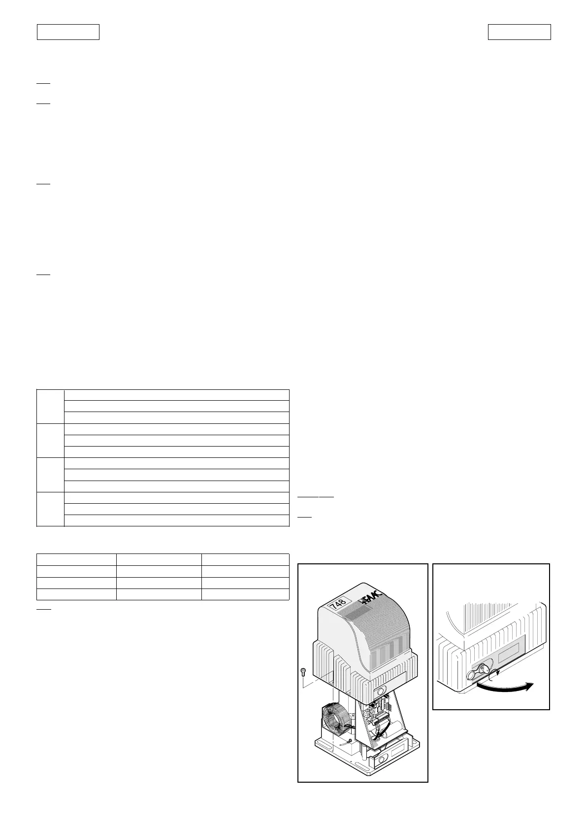
11) Fit the cover on the operator by means of the screws provided, as
shown in figure 15.
12. OPERATION OF ELECTRONIC CLUTCH
This is a very important device for safety. Its setting does not alter through
time, as the device is not subject to wear or setting changes.
It is active both at closing and opening. When it operates it reverses
motion direction without inhibiting automatic closing if enabled.
If it operates twice in succession, it moves to STOP position, disabling
any automatic command.
This is why: if the clutch operates twice, this means the obstacle is still
present and any further manoeuvres could be dangerous, thus obliging
the user to give an opening or closing command.
In that case the control unit executes an EMERGENCY procedure as
follows: full opening at slow speed up to the opening gate stop, followed
by automatic closing to enable the gate stops to re-synchronise
independently.
13. MANUAL OPERATION
Should the need arise to operate the gate manually because of a
power failure or malfunction, release it by means of the releasing device
(fig. 1 - ref. 6).
Proceed as follows:
• open the lid of the lock and insert the relative key in the lock (fig. 16);
• turn the key clockwise and open the cover of the releasing device
as shown in figure 16.
To re-lock the system, return the cover of the releasing device to its
initial position.
Important
: before giving a signal, ensure that the gate cannot be
moved manually.
N.B.:
re-lock always the operator with gate in closed position.
Fig. 16
Fig. 15
 Loading...