Do you have a question about the FAAC C850 and is the answer not in the manual?
Details manufacturer, address, declared product, and relevant EEC directives.
Details manufacturer, address, declared product, and relevant EEC directives.
Comprehensive safety guidelines for installers to ensure safe operation and installation.
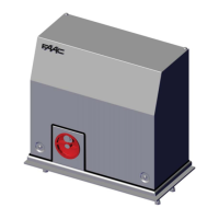
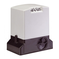
Introduces the C850 electromechanical operator, its features, and manual release.
Lists detailed technical specifications and components of the C850 operator.
Illustrates the physical dimensions of the C850 operator with key measurements.
Shows the typical electrical connections for a standard right-hand opening system.
Lists essential checks to ensure a safe and correct automated system installation.
Details the process of installing the foundation plate and preparing for electrical cables.
Guides the installer through positioning, securing, and adjusting the gearmotor assembly.
Explains the procedures for installing both weld-on and screw-on steel racks.
Provides crucial notes and torque specifications for successful rack installation.
Details steps for connecting the control board, including safety precautions and wiring.
Provides a detailed guide for adjusting limit switches using charts for stop space and deceleration.
Details final inverter settings, mechanical checks, and testing after limit switch adjustment.
Guides on checking all system components and demonstrating operation to the customer.
Explains how to manually move the gate and how to lock/unlock the operator.
Provides warnings, technical specifications, and a detailed layout of the E850 control unit.
Details connections for accessories on terminal board J1, including safety device configurations.
Illustrates how to connect photocells as safety devices using N.C. contacts.
Explains how to connect BUS 2easy photocells, including addressing and wiring diagrams.
Details the connection for the flashing lamp output on terminal board J2.
Specifies the connections for the main power supply to the E850 control unit.
Describes how to connect opening and closing limit switches using rapid connectors J3 and J5.
Explains how to use the DS1 dip-switch to set loop frequencies for vehicle detection.
Details the use of connector J4 for connecting radio accessories like Minidec and RP receivers.
Provides instructions for inverting connections for left-hand gate opening.
Illustrates the wiring differences for right-hand versus left-hand gate opening configurations.
Provides visual steps for connecting cables for right-hand and left-hand gate opening.
Explains how to enter and navigate the basic programming level for system configuration.
Describes how to load factory default settings and the impact on existing configurations.
Explains how to interpret BUS communication status signals and error indicators.
Details advanced programming parameters for fine-tuning system behaviour and outputs.
Explains how to set up, connect, and calibrate the integrated loop detector for vehicle detection.
Guides on checking the status of board LEDs and BUS system for correct start-up.
Confirms that the system operates correctly after programming and checks safety features.
Details how to access and use the expert level for advanced logic customization.
Explains how to use expert settings to personalize the system's operating logic.
Provides detailed tables for automatic and step-by-step operating logic behaviors.
Details logic tables for semi-automatic, photocell automatic, and dead-man operating modes.
Describes the Omron inverter control panel, its display, LEDs, and function keys.
Details the functions of the Mode, Enter, Increase, and Decrease keys on the inverter panel.
Provides step-by-step instructions for programming key inverter parameters like speed and acceleration times.
A comprehensive table listing default values for various inverter parameters.
Continues the table of default values for inverter parameters.
Lists inverter error codes and provides troubleshooting guidance for common issues like overload and overvoltage.
Describes the optional external programming keyboard and its features.
Provides essential safety rules, operational description, and manual operation guidance for users.
A logbook for recording maintenance activities, installations, and service details.
| Brand | FAAC |
|---|---|
| Model | C850 |
| Category | Garage Door Opener |
| Language | English |