17
ENGLISH
24 Vdc
3 W
C
M
24V
1 2 3 4 5 6 7 8 9 10 11 12
13 14 15 16 17
PE N L
EDGE
W.L.
TX-FSW
+
LIMITS ENCODER
MOTOR
ACCESSORIES
LAMP
MAIN
N
L
STOP
+
--
OPEN
B
A
OPEN
FSW
OP
FSW
CL
COM
OPEN
CLOSE
LAMP
PE
N
J1
J7
J5
J3
J6
24V
F1
F2
1 2 3 4 5 6 7 8 9 10 11 12
13 14 15 16 17
PE N L
EDGE
W.L.
TX-FSW
+
LIMITS ENCODER
MOTOR
ACCESSORIES
LAMP
MAIN
N
L
F
+
RADIO
FCA
FCC
OPEN
B
FSW
CL
STOP
SAFE
OPEN
A
FSW
STOP
+
--
OPEN
B
A
OPEN
FSW
OP
FSW
CL
COM
OPEN
CLOSE
LAMP
PE
N
ENCODER
EDGE
OP
-
J1
J7
J5
J3
J6
J2
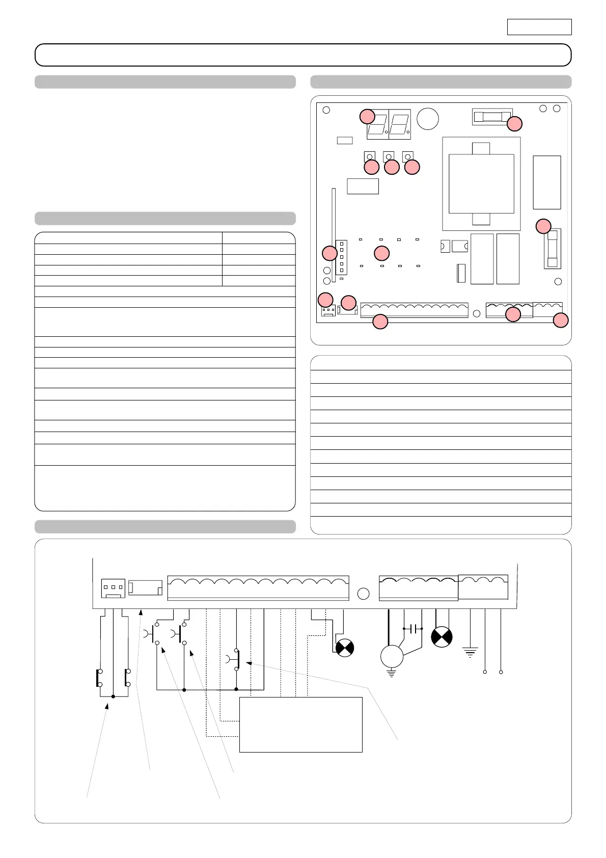
Fig. 1
NB.: The capacitor is supplied with the operator.
Fig. 2
TOTALLY OPEN
PARTIALLY OPEN
STOP
CONTROL BOARD 748D
DL SIGNALLING AND PROGRAMMING DISPLAY
Led INPUTS STATUS CONTROL LED
J1 LOW VOLTAGE TERMINAL BOARD
J2 CONNECTOR FOR DECODER/MINIDEC/RP RECEIVER
J3 ENCODER CONNECTOR
J5 LIMIT -SWITCH CONNECTOR
J6 MOTORS AND FLASHING LAMP CONNECTION TERMINAL BOARD
J7
POWER SUPPLY TERMINAL BOARD 115Vac(748D-115V)-230Vac(748D-230V
)
F1
MOTORS AND TRANSF. PRIMARY FUSE (748D 115V=F10A - 748D 230V=F 5A)
F2 LOW VOLTAGE AND ACCESSORIES FUSE (T 800mA)
F "F" PROGRAMMING PUSH-BUTTON
– "–" PROGRAMMING PUSH-BUTTON
+ "+" PROGRAMMING PUSH-BUTTON
F
F1
F2
J1
J2
J3
J5
J6
DL
–+
Model 748D-115V 748D-230V
Power supply
V~
( +6% -10%) 50 Hz
115 230
Absorbed power (W) 10 10
Motor max. load (W) 1200 1000
Accessories max. load (A) 0.5 0,5
Operating ambient temperature -20 °C +55 °C
Protection fuses 2 (see fig. 1)
Function logics Automatic / "Stepped" automatic /
Semi-automatic / Safety devices / Semi-automatic B / Dead-man C /
"Stepped" semi-automatic
Work time Programmable (from 0 to 4 min.)
Pause time Programmable (from 0 to 4 min.)
Thrust force Adjustable over 50 levels
Terminal board inputs Open / Partial opening / Safety devices at opng. /
Safety devices at clsng. / Stop / Edge / Power supply + Earth
On-connector inputs Opening and closing limit-switches / Encoder
Terminal board outputsFlashing lamp - Motor - 24 Vdc accessories power
supply - 24 Vdc indicator-light / Timed output. - Fail safe
Rapid connector 5-pin card connection for Minidec, Decoder or RP receivers
Programming 3 keys (+, -, F) and display, "basic" or "advanced" mode
Basic mode programmable functions Function logic - Pause time - Thrust
Force - Gate direction
Advanced mode programmable functions Torque at initial thrust - Braking -
Fail safe - Pre-flashing - Indicator-light/Timed output -
Opening and closing safety devices logic -
Encoder - Decelerations - Partial opening time -
Work time - Assistance request - Cycle counter
For connection of the
photocells and safety
devices, see paragraph
4.1.
BLUE
LIMIT-SWITCH
ENCODER
(optional)
1. WARNINGS
Important: Before attempting any work on the control board
(connections, maintenance), always turn off power.
- Install, upstream of the system, a differential thermal breaker with
adequate tripping threshold.
- Connect the earth cable to the appropriate terminal on the J7
connector of the equipment (see fig.2).
- Always separate power cables from control and safety cables
(push-button, receiver, photocells, etc.). To avoid any electric
noise, use separate sheaths or a shielded cable (with earthed
shield).
2. TECHNICAL SPECIFICATIONS
3. LAYOUT AND COMPONENTS
Led
J7
4. ELECTRIC CONNECTIONS
115Vac
(748D 115V)
max. 60W
-
230 Vac
(748D 230V)
max. 60W
115Vac 50-60Hz
(748D 115V)
-
230Vac 50-60Hz
(748D 230V)