E145 2 732783 - Rev.E
Translation of the original instructions
ENGLISH
1. TECHNICAL SPECIFICATIONS
CE DECLARATION OF CONFORMITY
The manufacturer
Company name:
FAAC S.p.A. Soc. Unipersonale
Address: Via Calari, 10 - 40069 Zola Predosa BOLOGNA - ITALY
hereby declares that the following product:
Description: control board
Model: E145
conforms to the essential safety requirements of the following ECC directives:
Low Voltage Directive 2014/35/EU
Electromagnetic Compatibility Directive 2014/30/EU
Directive ROHS 2011/65/EU
Furthermore, the following harmonised standards have been applied:
EN 60335-1:2012 + A11:2014 - EN 61000-6-2:2005 - EN 61000-6-3:2007 + A1:2011
Additional note: this product underwent tests in a typical uniform configuration (all products
manufactured by FAAC S.p.A.).
Bologna, January the 1
st
2016 CEO
INTENDED USE: this electronic board is designed and
built to control swing and/or sliding gates, which
control access of vehicles and pedestrians.
Thanks to the electronic board E145 and the new
Mains primary power supply With switching power supply from 90 V~ to 260 V~; 50/60 Hz
Power absorbed from mains stand By = 4W ; MAX ~ 800 W ; sleep < 2 W (can be activated via PC/MAC)
MAX motor load 800 W
Accessories power supply 24 V
"
MAX Accessories current +24V
"
MAX 500 mA ; BUS-2easy MAX 500 mA ; LOCK (FAAC) 12 V~/ 24 V
"
; LOCK (NON FAAC) 24 V
"
500mA
(3A peak)
Operating temperature da -20°C to +55°C
Power supply fuses F1 = F10 AH 250 V
2. INSTALLATION SEQUENCE
Remove the pictures collection from the centre of the instruction manual.
6. Set the electronic board, according to the system
and customer requirements: Chapter 3. Check the
connection of the motors: Paragraph 3.3.
7. Store the remote controls in use on the system:
- for SLH encoded remote controls: fig.
- for LC/RC encoded remote controls: fig.
8. Close the doors to perform SET-UP: Chapter 4.
9. According to the installed devices and the regu-
lations in force, set the functions of the board:
Paragraph 3.4.
10. Give an opening impulse to verify that the system
works correctly.
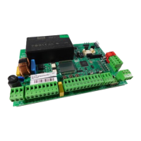
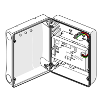
1. Secure the card into the enclosure and fit the pro-
tective cover: fig. .
2. Wire the electronic board: fig.
- to connect traditional photocells: fig.
- to connect and address BUS-2easy photocells:
fig.
- to connect the receiver module: fig.
- to connect any Bus encoders: terminal J10, fig.
ref. A.
3. Power the board E145.
4. Verify the status of the LEDs on board: fig. .
5. Verify the LEDs on any Bus encoders, depending
on the installation: fig. ref. B.
SAFEcoder absolute encoder (FAAC Patented), it is easier
to adapt existing systems in accordance with the law
without having to replace the existing automated
systems.