E721 14 532014 - Rev.E
BUS
2EASY
< OPEN A
RADIO XF
SETUP
OUT
-+
F
+
-
USB
< GND
< OPEN B / CLOSE
<STOP
<FSWOP
< GND
<FSWCL
<+24
< MAIN
(PE-N-L)
<B
ATTERY
<M
OTOR
<L
AMP
< LOCK
< LOCK
< LOCK
<PRIM
TRANS
F
< SEC
TRANS
F
RADIO1
RADIO2
ER
ROR
POWER
RELEASE
BATTERY
FC
A
FC
C
< (1)
< (2)
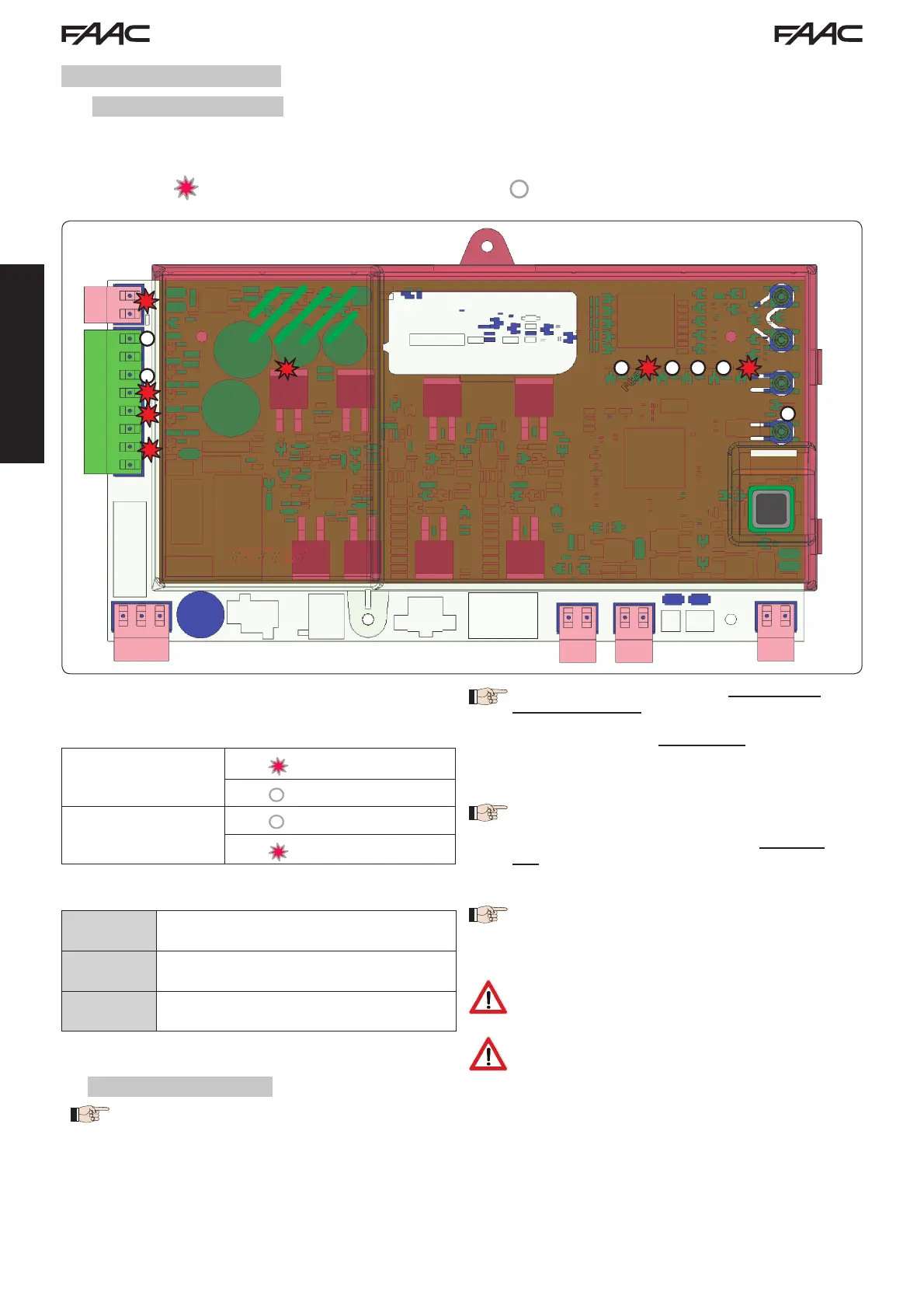
Fig. 16
< SAFE
/ SAFE
ENGLISH
7 OPERATIONAL START-UP
7.1
CHECKING THE LEDS
After making all the connections and powering the board, check the status of the LEDs against the status of the inputs
in the following table (in Fig. 16, the condition where the automated system is closed in stand-by).
These LEDs indicate the status of the board inputs and are of considerable importance to automated system movement:
Note that:
LED ON = contact closed
LED OFF = contact open
ERROR LED flashing indicates alarm in
progress (situation does not impair gate
operation)
Automated system
CLOSED
FCA
FCC FCC engaged
Automated system
OPEN
FCA
FCA engaged
FCC
Leds FCA and FCC represent the N.C. contacts of the limit
switch built into the board that open when engaged and
turn off the associated LED:
ERROR LED on with a fixed light indicates
an error in progress (situation that locks
operation until the cause of the error has
been removed)
Fixed ON Mains-powered
Flashing Battery-powered
Off Board off
Tab. 3 - Description of POWER LED
7.2
BATTERY OPERATION
ATTENTION
To optimise energy consumption and protect the charge, during battery operation, when the automated system is
stopped and the system is on stand-by, the LCD1 display, the BUS 2easy LED and the FCC and FCA LED will be off
while the POWER LED flashes.
In this phase it is in any case possible to view the state of the automated system. To do this it is sufficient to briefly press
“+” on the board. Following brief pressure, the LCD1 display shows the state of the automated system for approximately
2 seconds to then go off again. Instead, during normal operation all the diagnostic LEDs and the display state signals
become consistent with the state of the automated system (see Fig. 16).
The STOP (SAFE), FSW CL, FSW OP, OPEN B inputs
configured as SAFE are safety inputs with N.C.
(Normally Closed) contact and therefore the
corresponding LEDs must be ON when the
automated system is at rest, and off when
the connected device is used.
The OPEN A, OPEN B/CLOSE inputs are inputs
with N.O. (Normally Open) contact and
therefore the corresponding LEDs must be
OFF when the automated system is at rest,
and on when the connected device is used.
When using equipment programmed as
SLAVE the LEDs corresponding to terminal
board J13 must be off.

 Loading...